ProTron LED
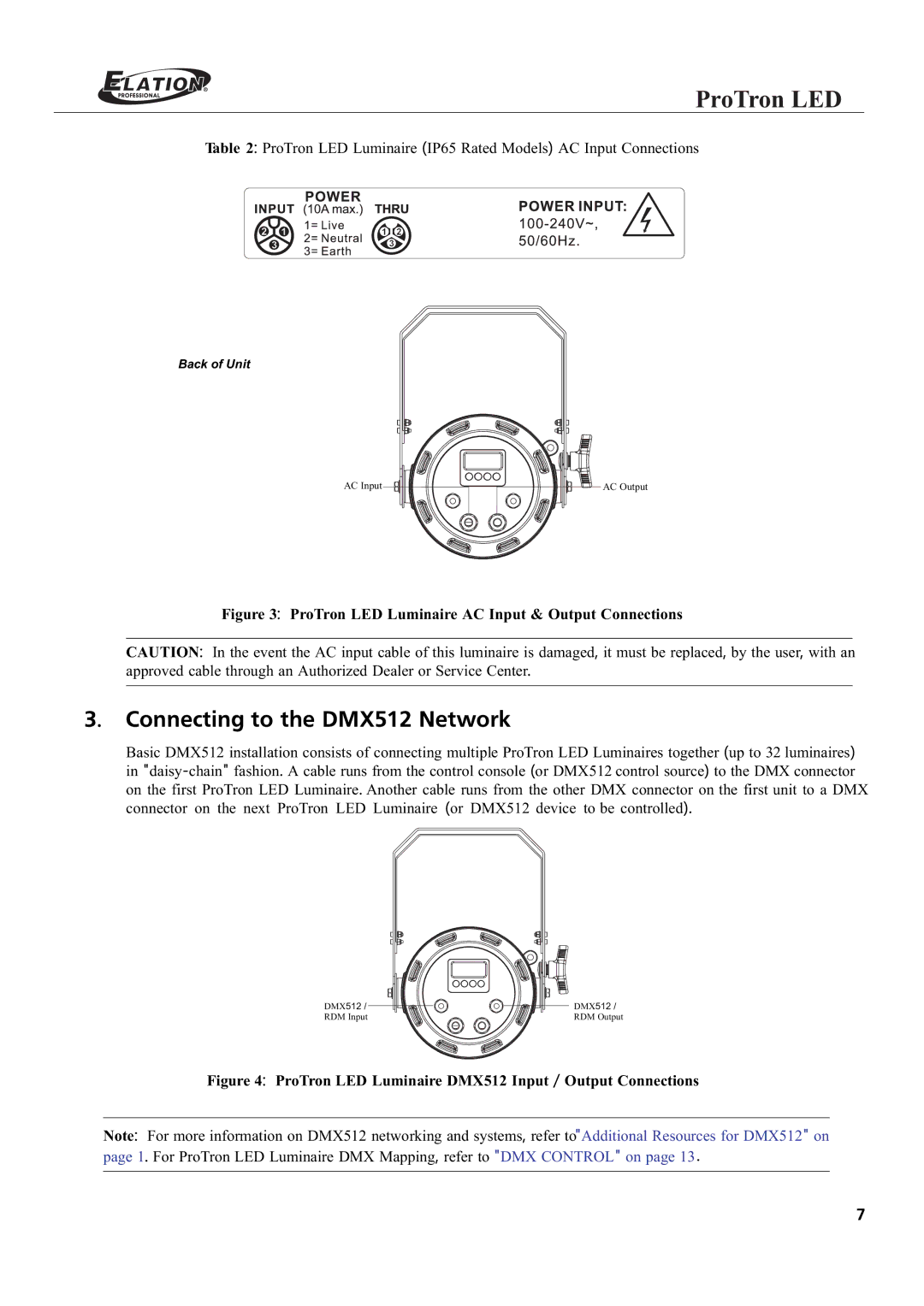
Table 2: ProTron LED Luminaire (IP65 Rated Models) AC Input Connections
Back of Unit
AC Input ![]()
![]() AC Output
AC Output
Figure 3: ProTron LED Luminaire AC Input & Output Connections
CAUTION: In the event the AC input cable of this luminaire is damaged, it must be replaced, by the user, with an approved cable through an Authorized Dealer or Service Center.
3. Connecting to the DMX512 Network
Basic DMX512 installation consists of connecting multiple ProTron LED Luminaires together (up to 32 luminaires) in
DMX512 / ![]()
![]()
![]()
![]()
RDM Input
DMX512 /
RDM Output
Figure 4: ProTron LED Luminaire DMX512 Input / Output Connections
Note: For more information on DMX512 networking and systems, refer to"Additional Resources for DMX512" on page 1. For ProTron LED Luminaire DMX Mapping, refer to "DMX CONTROL" on page 13.
7