R300 specifications
The Electro-Voice R300 is a highly regarded wireless microphone system designed to meet the needs of professionals in various environments, including live performances and studio recordings. This system stands out for its reliability, durability, and exceptional audio quality, making it an ideal choice for musicians, public speakers, and event hosts.One of the main features of the Electro-Voice R300 is its diverse frequency range. It operates on UHF (Ultra High Frequency), which allows for clear signal transmission with minimal interference. The R300 has multiple frequency options, enabling users to select the best channel for their specific location, thereby ensuring optimal performance in any setting. This flexibility is especially beneficial in crowded venues where many devices might compete for wireless bandwidth.
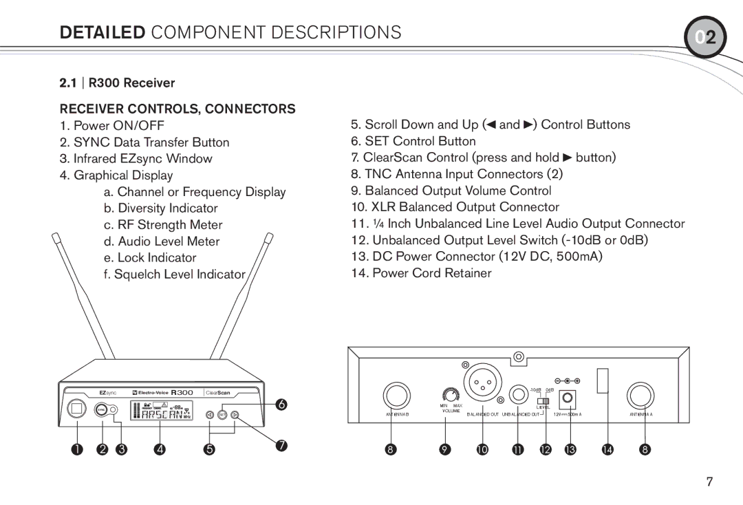
The system includes a robust receiver that provides excellent signal reception. The R300 features an easy-to-read LCD display that shows vital information, such as battery status, signal strength, and frequency selection. This user-friendly interface allows for quick adjustments on the fly, making it easier for performers to focus on their art without technical distractions.
Another key characteristic of the R300 is its diverse microphone options. Users can choose between handheld transmitters and bodypack transmitters, allowing for versatility depending on the performance type. The handheld microphone is ideal for vocalists, while the bodypack transmitter suits instruments or lavalier microphones for presenters.
The receiver's design is engineered for ruggedness and portability. It features a compact, lightweight body that can be easily mounted on a rack or set up on a tabletop, allowing for seamless integration into various setups. The system also supports automatic frequency scanning, quickly identifying the best available channels and simplifying setup time.
Battery life is another strong point of the Electro-Voice R300. With energy-efficient components, the system can provide extended use, ensuring that performers are not interrupted by power failures. The transmitters are designed for easy access, making it simple to replace batteries quickly during performances.
In summary, the Electro-Voice R300 wireless microphone system combines advanced technology, user-friendly features, and durable construction. Its exceptional audio quality, versatile microphone options, and robust receiver design make it a top choice for audio professionals seeking reliable performance in diverse settings. Whether for live shows, public speaking engagements, or studio recordings, the R300 delivers outstanding results, ensuring that every word and note is heard with clarity and precision.

