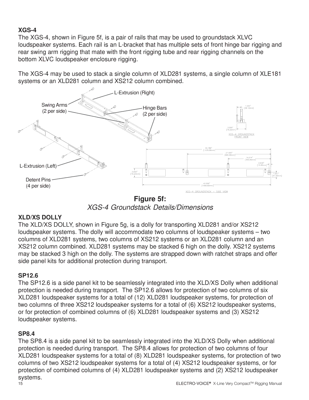
X-LineVery Compact Rigging Manual
ELECTRO-VOICE X-LineVery CompactTM Rigging Manual
Table of Contents
Rigging-SafetyWarning
0. Introduction
Figure 1a XLD281 Loudspeaker System
HFLF
Top View LFHF
Rear View
Front View Without Grille
1.1 Overview of the XLVC Flying System
1. X-LineVery Compact Rigging System
1.2 XLVC Enclosure Rigging Hardware Details
Typical XLVC Flying System without Coupler Beam
Figure 3b
Quick-ReleasePins
Quick-ReleasePins
Quick-ReleasePins During Transport Hinge Bar Must
Figure 4a
Front View With Grille
Side View
Hole Detail
Figure 4b
Front View With Grille
Side View
Rear View
Figure 4c
Front View
Hole Detail Scale 3 1 Rear View
Only
Figure 5a
XLD GRID Rigging Dimensions and Weights
Figure 5b
XLE GRID Rigging Dimensions and Weights
Figure 5c
CBEAM Rigging Dimensions and Weights
Figure 5d
Figure 5e
XLVC-BGKBottom Grid Kit Contents
AGCD Adapter Grid Dimensions and Weights
Figure 5f
XGS-4Groundstack Details/Dimensions
Figure 5g
XLD/XS Dolly Shown with SP8.4 Kit Installed
32. Dolly
XLD/XS Dolly Cover Sample Column of 4 XLD281’s
2. XLVC Rigging and Flying Techniques
2.1 Array Considerations
2.2 Rigging XLVC Enclosures Together
Rigging XLD281 or XLE181 Enclosures Together
Figure 6a
audience only sees XLD281’s
Coupler Beam XS212 Enclosures XLD281 Enclosures
Side View
XS212’s using Interactive Rigging
using Interactive Rigging
Figure 6b
Figure 6c
Figure 7a
Rigging XLD281 or XLE181 Systems Together
Rigging XS212 Systems Together
Figure 7b
Rigging XS212 Enclosures Together
Rigging XS212 and XLD281 Enclosures Together
Figure 7c
Rigging XLD281 and XS212 Systems Together
Page
Figure 8a
Step
Step
Step
XLD GRID and XLE GRID Rigging Configurations
Figure 8b
ELECTRO-VOICE X-LineVery CompactTM Rigging Manual
2.4 Rigging the XLVC Grids and the CBEAM
Figure 9a
CBEAM Rigging Assembly
Figure 9c
Figure 9b
Figure 9d
Figure 9e
CBEAM Shipping/Transport Configuration
Assembling the XLVC-BGKand
Secondary Grid at the Bottom of an Array
Figure 10b
XLVC Array with XLVC-BGKand
2.6 Using the AGCD with XLVC and XLC Systems
Using the AGCD Adapter Grid
Figure 11a
Figure 11b
Step 1 Stacking Arrays onto the
Step 2 Stacking Arrays onto the
XLD/XS Dolly - Enclosure Attachment
XLD/XS Dolly - Grid Attachment
Page
3.2 Structural Rating Overview
Figure 13a
XLD281 Simplified Structural Ratings
Figure 13b
Figure 13c
XLE181 Simplified Structural Ratings
XS212 Simplified Structural Ratings
Each Figure 13 includes a graph of the working-load weight-versus-anglelimit rating for the XLVC enclosures. This working-loadweight limit is applicable to every enclosure in an array, and in- cludes the weight of that enclosure plus the total weight of all enclosures, rigging hardware and cabling suspended below it. The enclosure elevation angle is the vertical angle of that enclosure, where 0 represents an upright enclosure facing straight ahead 0 elevation angle. These work- ing-Ioad-versus-anglelimits take into account the complex forces generated in the front hinge bars, the rear swing arms, the quick-releasepins, the rigging tubes and channels, the enclosures and the optional pull-upline, as a result of the complex weight distribution throughout the array
3.4 Complex Structural-RatingAnalysis
Figure 14a
Total Column Weight Working-LoadLimit
XLD281 Hinge Bar Structural Ratings
XLD281 Swing Arm Structural Ratings
Figure 14b
Total Column Weight Working-LoadLimit
XLE181 Hinge Bar Structural Ratings
XLE181 Swing Arm Structural Ratings
Figure 14c
Total Column Weight Working-LoadLimit
XS212 Hinge Bar Structural Ratings
XS212 Swing Arm Structural Ratings
XLD281, XLE181, and XS212 Overall Enclosure Structural-StrengthRatings
Figure 15a
Figure 15b
XLD GRID Complex Structural Ratings
XLE GRID Complex Structural Ratings
CBEAM Complex Structural-StrengthRatings
Figure 15c
CBEAM Complex Structural Ratings
Figure 15d
AGCD Adapter Grid Complex Structural Ratings
4. Rigging Inspection and Precautions
Electro-VoiceXLVC Loudspeaker Systems
Coupler Beam CBeam Assemblies Prior to each use, inspect the CBeam assemblies for any cracks, burrs, deformations, corrosion or missing or damaged components that could reduce the CBeam assembly strength. Replace any CBeam assemblies that are damaged or missing hardware. Always double check that each CBeam assembly is securely locked to the spreader bars on the grids below. Never exceed the limitations or maximum recommended load for the CBeam assemblies
Rigging References
References
Mechanical Engineering References
Websites
References
ELECTRO-VOICE X-LineVery CompactTM Rigging Manual