| LF1 | HF | LF2 |
| |||||||
|
|
|
|
|
|
|
|
|
|
|
|
|
|
|
|
|
|
|
|
|
|
|
|
|
|
|
|
|
|
|
|
|
|
|
|
|
|
|
|
|
|
|
|
|
|
|
|
|
|
|
|
|
|
|
|
|
|
|
|
|
|
|
|
|
|
|
|
|
|
|
|
|
|
|
|
|
|
|
|
|
|
|
|
|
|
|
|
|
|
|
|
|
|
|
|
|
|
|
|
|
|
|
|
|
|
|
|
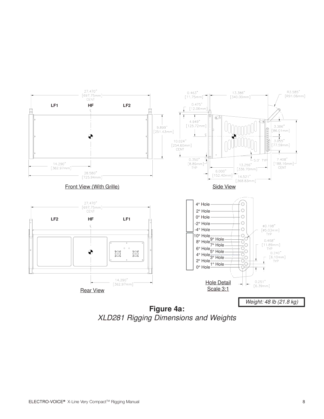
Front View (With Grille) | Side View |
LF2 | HF | LF1 |
![]() Full Range Only Subwoofer Only
Full Range Only Subwoofer Only
4° Hole
2° Hole
0° Hole
10° Hole
8° Hole9° Hole
7° Hole
6° Hole5° Hole
4° Hole3° Hole
2° Hole
0° Hole1° Hole ![]()
![]()
| Hole Detail |
Rear View | Scale 3:1 |
|
Figure 4a:
XLD281 Rigging Dimensions and Weights
Weight: 48 lb (21.8 kg)
8 |