Manuals
/
Electro-Voice
/
Home Audio
/
Speaker System
Electro-Voice
X-Line Very Compact (XLVC)
manual
ELECTRO-VOICEX-Line Very CompactTM Rigging Manual
Models:
X-Line Very Compact (XLVC)
1
39
56
56
Download
56 pages
25.5 Kb
36
37
38
39
40
41
42
43
Xlvc Rigging Accessory Details
Cbeam Rigging Assembly
Weight
Safety
Page 39
Image 39
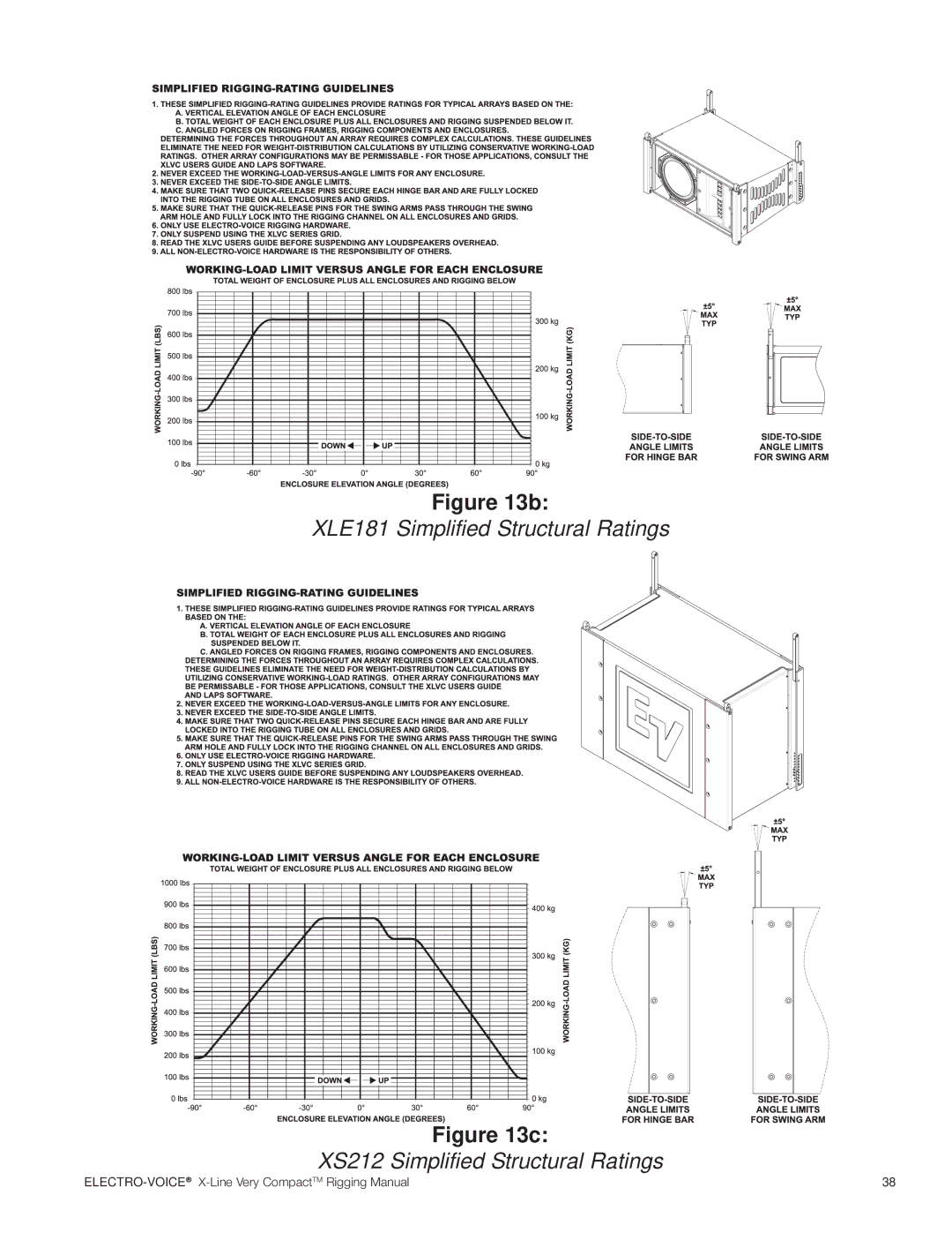
Figure 13b:
XLE181 Simplified Structural Ratings
Figure 13c:
XS212 Simplified Structural Ratings
ELECTRO-VOICE
®
X-Line
Very Compact
TM
Rigging Manual
38
Page 38
Page 40
Page 39
Image 39
Page 38
Page 40
Contents
Line Very Compact Rigging Manual
Table of Contents
Rigging-Safety Warning
XLD281 Loudspeaker System
Introduction
XLE181 Loudspeaker System
Line Very Compact Rigging System
Overview of the Xlvc Flying System
Xlvc Enclosure Rigging Hardware Details
Typical Xlvc Flying System Without Coupler Beam
Rigging Hardware
XS212 Rigging Hardware
Weight 48 lb 21.8 kg
XLD281 Rigging Dimensions and Weights
XLE181 Rigging Dimensions and Weights
Front View
XS212 Rigging Dimensions and Weights
Xlvc Rigging Accessory Details
XLD Grid Rigging Dimensions and Weights
XLE Grid
XLE Grid Rigging Dimensions and Weights
XLVC-BGK
Cbeam Rigging Dimensions and Weights
Agcd Adapter Grid Dimensions and Weights
XLVC-BGK Bottom Grid Kit Contents
XGS-4 Groundstack Details/Dimensions
SP12.6
SP8.4
XLD/XS Dolly
Xlvc Rigging and Flying Techniques
Array Considerations
Rigging Xlvc Enclosures Together
Front View
Front ViewSide ViewFront ViewSide View
Rigging XLD281 or XLE181 Systems Together
Rigging XS212 Enclosures Together
Rigging XS212 Systems Together
Rigging XS212 and XLD281 Enclosures Together
Rigging XLD281 and XS212 Systems Together
Rigging the Xlvc Loudspeaker Systems and Xlvc Grids
XLD Grid and XLE Grid Rigging Assembly
XLD Grid and XLE Grid Rigging Configurations
Rigging the Xlvc Grids and the Cbeam
Cbeam Rigging Assembly
Cbeam Dual-Array Configuration Using Grid Positions a and C
Cbeam Single-Array Configuration Using Grid Position B
Cbeam Pick Up Options
Using the XLVC-BGK and Grid for Pull Up
Cbeam Shipping/Transport Configuration
Assembling the XLVC-BGK
Using the Agcd with Xlvc and XLC Systems
XLVC-BGK
XLD/XS Dolly Lift
Column of Enclosures
Rigging an Array from the Xlvc Dollies
Working-Load Limit and Safety Factor Definitions
Structural Rating Overview
Simplified Structural-Rating Guidelines
XLD281 Simplified Structural Ratings
ELECTRO-VOICEX-Line Very CompactTM Rigging Manual
ELECTRO-VOICEX-Line Very CompactTM Rigging Manual
XLD281, XLE181 and XS212 Complex Structural-Strength Ratings
Complex Structural-Rating Analysis
Xld281 Hinge Bar Working-Load-Limit Structural Ratings
XLD281 Complex Structural Ratings
Xle181 Hinge Bar Working-Load-Limit Structural Ratings
XLE181 Complex Structural Ratings
Xs212 Hinge Bar Working-Load-Limit Structural Ratings
XS212 Complex Structural Ratings
ELECTRO-VOICEX-Line Very CompactTM Rigging Manual
ELECTRO-VOICEX-Line Very CompactTM Rigging Manual
Cbeam Complex Structural-Strength Ratings
Agcd Complex Structural-Strength Ratings
Cbeam Complex Structural Ratings
Electro-Voice Structural-Analysis Procedures
Agcd Adapter Grid Complex Structural Ratings
Wind Loading
Electro-Voice Xlvc Loudspeaker Systems
Rigging Inspection and Precautions
ELECTRO-VOICEX-Line Very CompactTM Rigging Manual
References
Rigging References
Mechanical Engineering References
Websites
ELECTRO-VOICEX-Line Very CompactTM Rigging Manual
ELECTRO-VOICEX-Line Very CompactTM Rigging Manual
Telex Communications, Inc /2006 Part Number 38110-429 Rev a
Top
Page
Image
Contents