Electro-Voice X-Line Very Compact (XLVC) manual Using the AGCD with XLVC and XLC Systems

Models: X-Line Very Compact (XLVC)

1 56
Download 56 pages 25.5 Kb
Page 33
Image 33
2.6 Using the AGCD with XLVC and XLC Systems

2.6 Using the AGCD with XLVC and XLC Systems

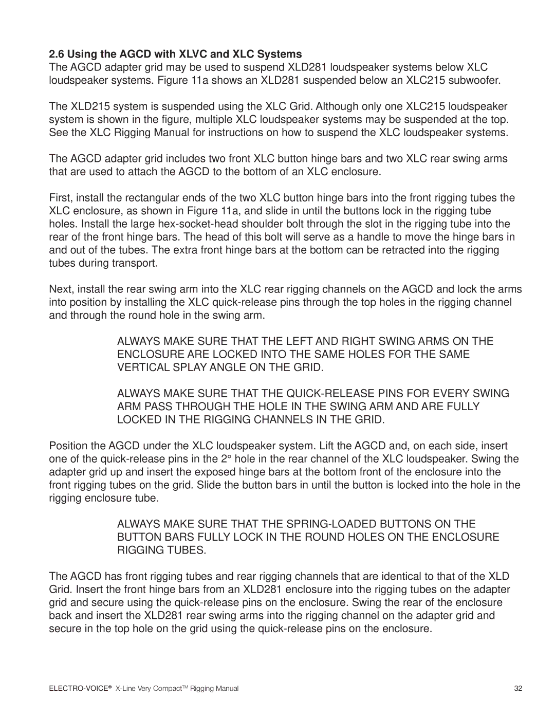
The AGCD adapter grid may be used to suspend XLD281 loudspeaker systems below XLC loudspeaker systems. Figure 11a shows an XLD281 suspended below an XLC215 subwoofer.

The XLD215 system is suspended using the XLC Grid. Although only one XLC215 loudspeaker system is shown in the figure, multiple XLC loudspeaker systems may be suspended at the top. See the XLC Rigging Manual for instructions on how to suspend the XLC loudspeaker systems.

The AGCD adapter grid includes two front XLC button hinge bars and two XLC rear swing arms that are used to attach the AGCD to the bottom of an XLC enclosure.

First, install the rectangular ends of the two XLC button hinge bars into the front rigging tubes the XLC enclosure, as shown in Figure 11a, and slide in until the buttons lock in the rigging tube holes. Install the large hex-socket-head shoulder bolt through the slot in the rigging tube into the rear of the front hinge bars. The head of this bolt will serve as a handle to move the hinge bars in and out of the tubes. The extra front hinge bars at the bottom can be retracted into the rigging tubes during transport.

Next, install the rear swing arm into the XLC rear rigging channels on the AGCD and lock the arms into position by installing the XLC quick-release pins through the top holes in the rigging channel and through the round hole in the swing arm.

ALWAYS MAKE SURE THAT THE LEFT AND RIGHT SWING ARMS ON THE ENCLOSURE ARE LOCKED INTO THE SAME HOLES FOR THE SAME VERTICAL SPLAY ANGLE ON THE GRID.

ALWAYS MAKE SURE THAT THE QUICK-RELEASE PINS FOR EVERY SWING ARM PASS THROUGH THE HOLE IN THE SWING ARM AND ARE FULLY LOCKED IN THE RIGGING CHANNELS IN THE GRID.

Position the AGCD under the XLC loudspeaker system. Lift the AGCD and, on each side, insert one of the quick-release pins in the 2° hole in the rear channel of the XLC loudspeaker. Swing the adapter grid up and insert the exposed hinge bars at the bottom front of the enclosure into the front rigging tubes on the grid. Slide the button bars in until the button is locked into the hole in the rigging enclosure tube.

ALWAYS MAKE SURE THAT THE SPRING-LOADED BUTTONS ON THE BUTTON BARS FULLY LOCK IN THE ROUND HOLES ON THE ENCLOSURE RIGGING TUBES.

The AGCD has front rigging tubes and rear rigging channels that are identical to that of the XLD Grid. Insert the front hinge bars from an XLD281 enclosure into the rigging tubes on the adapter grid and secure using the quick-release pins on the enclosure. Swing the rear of the enclosure back and insert the XLD281 rear swing arms into the rigging channel on the adapter grid and secure in the top hole on the grid using the quick-release pins on the enclosure.

ELECTRO-VOICE®X-Line Very CompactTM Rigging Manual

32

Page 33
Image 33
Electro-Voice X-Line Very Compact (XLVC) manual Using the AGCD with XLVC and XLC Systems