5Grill Assembly
IMPORTANT: Remove all protective plastic film from stainless steel parts prior to assembly/use. This film is installed at the factory to prevent damage that could occur during shipment and handling.
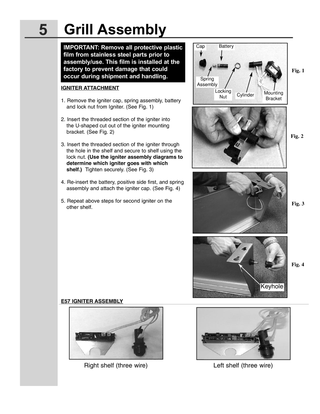
IGNITER ATTACHMENT
1.Remove the igniter cap, spring assembly, battery and lock nut from Igniter. (See Fig. 1)
2.Insert the threaded section of the igniter into the
3.Insert the threaded section of the igniter through the hole in the shelf and secure to shelf using the lock nut. (Use the igniter assembly diagrams to determine which igniter goes with which shelf.) Tighten securely. (See Fig. 3)
4.
5.Repeat above steps for second igniter on the other shelf.
Cap Battery
Spring
Assembly
Locking Cylinder Mounting
NutBracket
Fig. 1
Fig. 2
Fig. 3
Fig. 4
Keyhole
E57 IGNITER ASSEMBLY
Right shelf (three wire) | Left shelf (three wire) |