Gas Requirements 10
L.P. Gas Installation
Electrolux Gas Grills that are set to operate with L.P. gas come with a high capacity hose and regulator
assembly. (Note: Only use the pressure regulator and hose assembly supplied with the grill or a replacement pressure regulator and hose assemblies specified by Electrolux). This assembly is designed to connect directly to a standard 20 lb. L.P. cylinder.
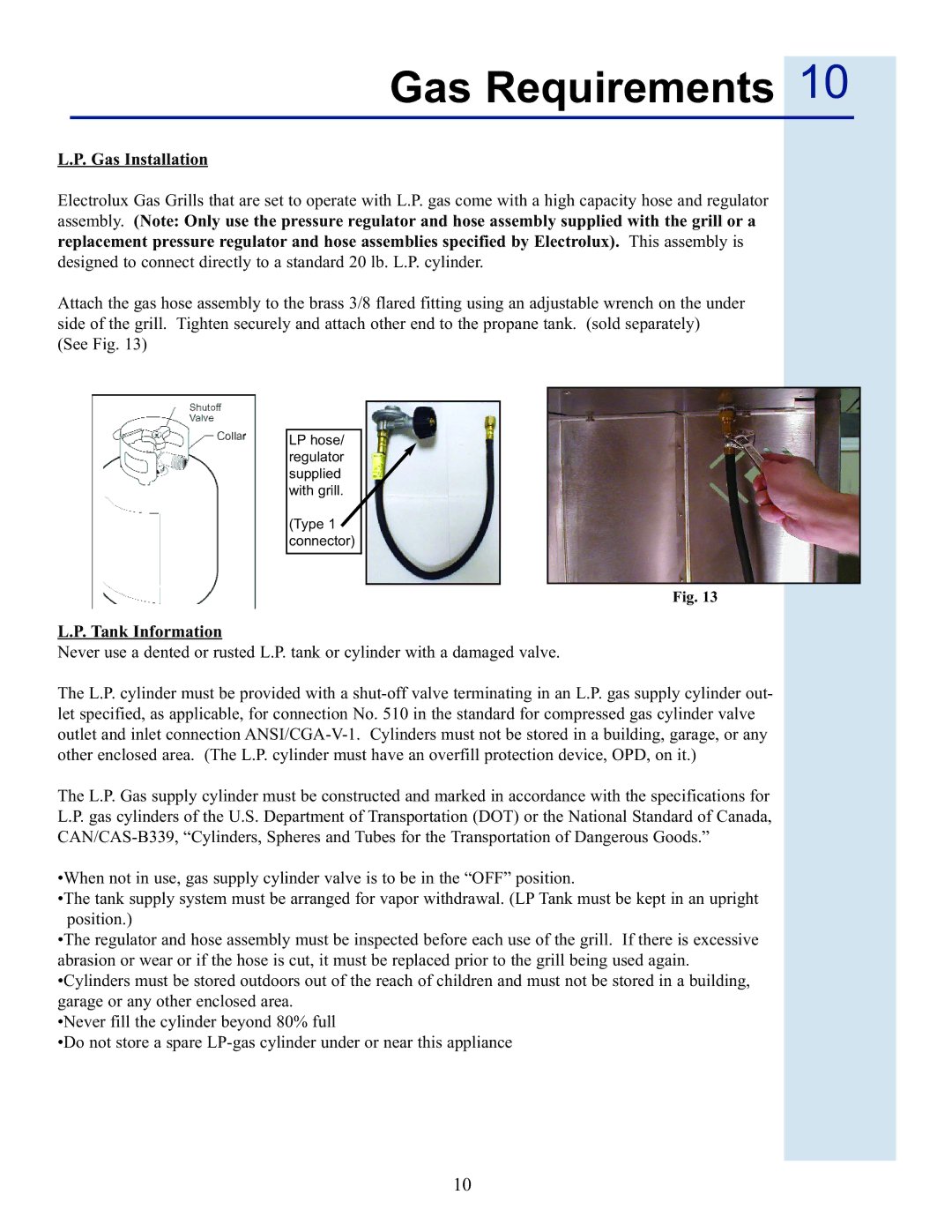
Attach the gas hose assembly to the brass 3/8 flared fitting using an adjustable wrench on the under side of the grill. Tighten securely and attach other end to the propane tank. (sold separately)
(See Fig. 13)
LP hose/ regulator supplied with grill.
(Type 1 connector)
Fig. 13
L.P. Tank Information
Never use a dented or rusted L.P. tank or cylinder with a damaged valve.
The L.P. cylinder must be provided with a
The L.P. Gas supply cylinder must be constructed and marked in accordance with the specifications for L.P. gas cylinders of the U.S. Department of Transportation (DOT) or the National Standard of Canada,
•When not in use, gas supply cylinder valve is to be in the “OFF” position.
•The tank supply system must be arranged for vapor withdrawal. (LP Tank must be kept in an upright position.)
•The regulator and hose assembly must be inspected before each use of the grill. If there is excessive abrasion or wear or if the hose is cut, it must be replaced prior to the grill being used again. •Cylinders must be stored outdoors out of the reach of children and must not be stored in a building, garage or any other enclosed area.
•Never fill the cylinder beyond 80% full
•Do not store a spare
10