Grill Assembly 4
Note: Prior to assembly remove protective film from stainless steel parts
Assembly requires: 4 tools and a Friend
Tools required:
1/4” socket wrench | Cap |
1/2” socket wrench |
|
adjustable wrench |
|
scissors |
|
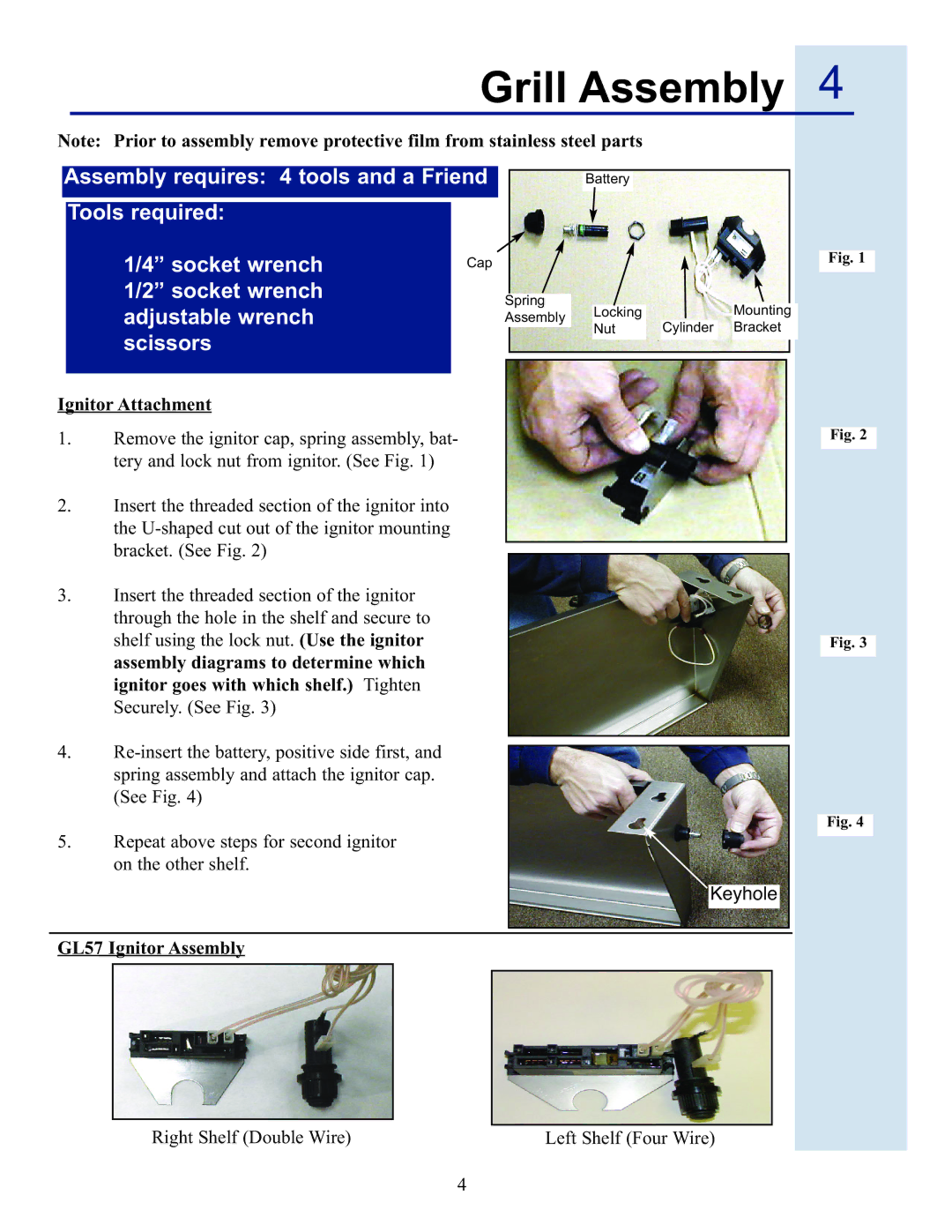
Ignitor Attachment
1.Remove the ignitor cap, spring assembly, bat- tery and lock nut from ignitor. (See Fig. 1)
2.Insert the threaded section of the ignitor into the
3.Insert the threaded section of the ignitor through the hole in the shelf and secure to shelf using the lock nut. (Use the ignitor assembly diagrams to determine which ignitor goes with which shelf.) Tighten Securely. (See Fig. 3)
4.
5.Repeat above steps for second ignitor on the other shelf.
Battery
Fig. 1
Spring |
|
|
|
|
|
|
| |
| Locking |
|
|
| Mounting | |||
Assembly |
|
|
|
| ||||
| Nut |
| Cylinder |
| Bracket | |||
|
|
|
|
| ||||
|
| |||||||
|
|
|
|
|
|
|
|
|
|
|
|
|
|
|
|
|
|
Fig. 2
Fig. 3
Fig. 4
Keyhole
GL57 Ignitor Assembly
Right Shelf (Double Wire) | Left Shelf (Four Wire) |
4