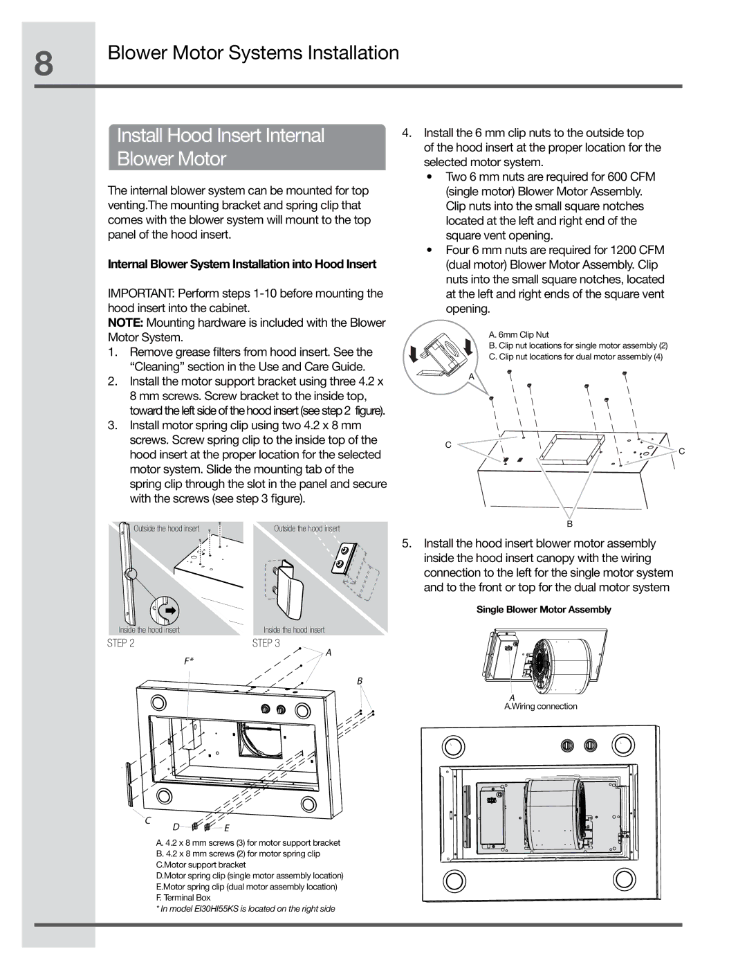
EI30HI55KS, EI48HI55KS, EI36HI55KS specifications
The Electrolux EI36HI55KS, EI48HI55KS, and EI30HI55KS are three exceptional models from Electrolux's line of refrigerators that combine cutting-edge technology with user-friendly features, making them ideal additions to modern kitchens.The EI36HI55KS is a standout model that offers a spacious 36-inch width and a sophisticated design. This refrigerator is equipped with TwinTech Freshness Control, ensuring both the refrigerator and freezer compartments maintain optimal humidity levels. This technology keeps fruits and vegetables fresh longer, preventing spoilage and waste. The model also features a total frost-free system, eliminating the hassle of manual defrosting while maintaining constant temperature and humidity in the fridge. With a sleek stainless-steel finish, it enhances the aesthetic appeal of any kitchen.
The EI48HI55KS model offers a larger 48-inch width, making it perfect for larger households or those who appreciate extra storage space. This unit also features the advanced TwinTech Freshness Control technology, ensuring that ingredients stay fresh while also providing a dedicated crisper drawer for fruits and vegetables. Additionally, it comes with a customizable temperature control system, allowing users to select the exact temperature for specific food items. The ice maker and water dispenser add convenience for those who enjoy chilled beverages, and the energy-efficient design ensures that it doesn’t add significantly to household energy bills.
The EI30HI55KS is a more compact model at 30 inches, making it an ideal choice for smaller kitchens without sacrificing functionality. This refrigerator also embraces the TwinTech Freshness Control system and features an attractive stainless-steel finish. The adjustable shelving system allows users to optimize their storage, while the efficient LED lighting illuminates the interior, making it easy to find ingredients. Its sleek and modern design fits seamlessly into any kitchen decor.
In summary, the Electrolux EI36HI55KS, EI48HI55KS, and EI30HI55KS refrigerators are all excellent choices for consumers seeking quality and innovation. With features such as TwinTech Freshness Control, customizable temperature settings, and energy-efficient designs, these models cater to a wide range of needs. Whether you require a spacious family-sized unit or a compact refrigerator for a smaller space, Electrolux has a solution that delivers on both performance and style.

