Installation Instructions
6 INSTALLATION HARDWARE
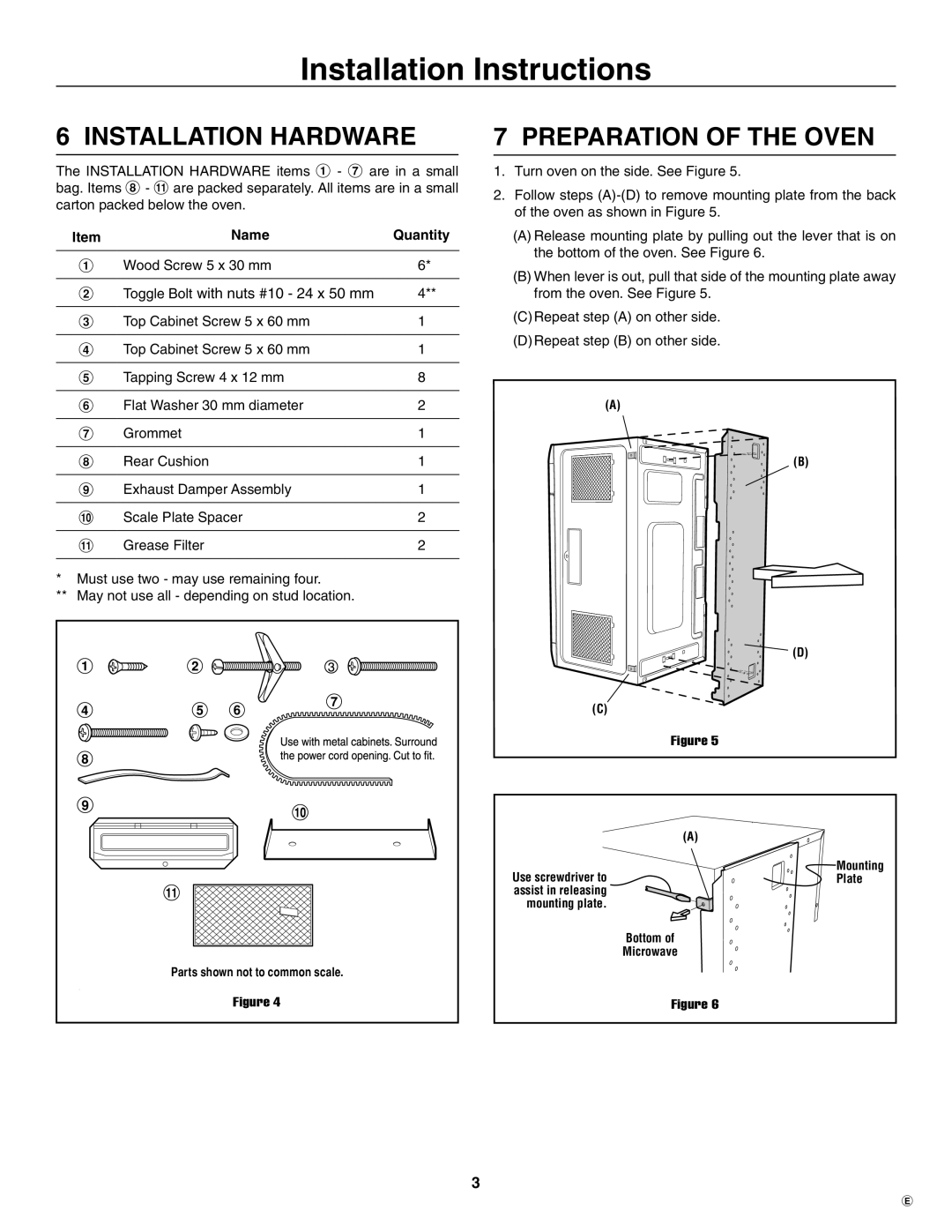
The INSTALLATION HARDWARE items 1 - 7 are in a small bag. Items 8 - " are packed separately. All items are in a small carton packed below the oven.
Item | Name | Quantity |
|
|
|
1 | Wood Screw 5 x 30 mm | 6* |
|
|
|
2 | Toggle Bolt with nuts #10 - 24 x 50 mm | 4** |
|
|
|
3 | Top Cabinet Screw 5 x 60 mm | 1 |
|
|
|
4 | Top Cabinet Screw 5 x 60 mm | 1 |
|
|
|
5 | Tapping Screw 4 x 12 mm | 8 |
|
|
|
6 | Flat Washer 30 mm diameter | 2 |
|
|
|
7 | Grommet | 1 |
|
|
|
8 | Rear Cushion | 1 |
|
|
|
9 | Exhaust Damper Assembly | 1 |
|
|
|
! | Scale Plate Spacer | 2 |
|
|
|
" | Grease Filter | 2 |
|
|
|
*Must use two - may use remaining four.
**May not use all - depending on stud location.
Parts shown not to common scale.
Figure 4
7 PREPARATION OF THE OVEN
1.Turn oven on the side. See Figure 5.
2.Follow steps
(A)Release mounting plate by pulling out the lever that is on the bottom of the oven. See Figure 6.
(B)When lever is out, pull that side of the mounting plate away from the oven. See Figure 5.
(C)Repeat step (A) on other side.
(D)Repeat step (B) on other side.
(A)
(B)
![]() (D)
(D)
(C)
Figure 5
| (A) |
Use screwdriver to | Mounting |
Plate | |
assist in releasing |
|
mounting plate. |
|
| Bottom of |
| Microwave |
Figure 6
E
