INSTALLATION INSTRUCTIONS
2.1FRONT PANELS (A) and (B)
(1)
Fig.6 Front panel
DUnscrew screws (1 or 3). Also, in the case of a
DPull the panel away forwards and downwards.
2.2CONTROL PANEL (C)
(2)
(1)
a | b |
(3)
Fig. 7 Control panel
c
DRemove the knob.
DLoosen the screws underneath (1 / Fig.7a) and remove the base plate.
DLoosen the screws (2 / Fig.7b) and 3 / Fig.7c)
DRemove the panel.
2.3OVEN, STORAGE SPACE, HOT CABINET
D Remove panels A, B and C. D Undo screws (5).
D Pull out element.
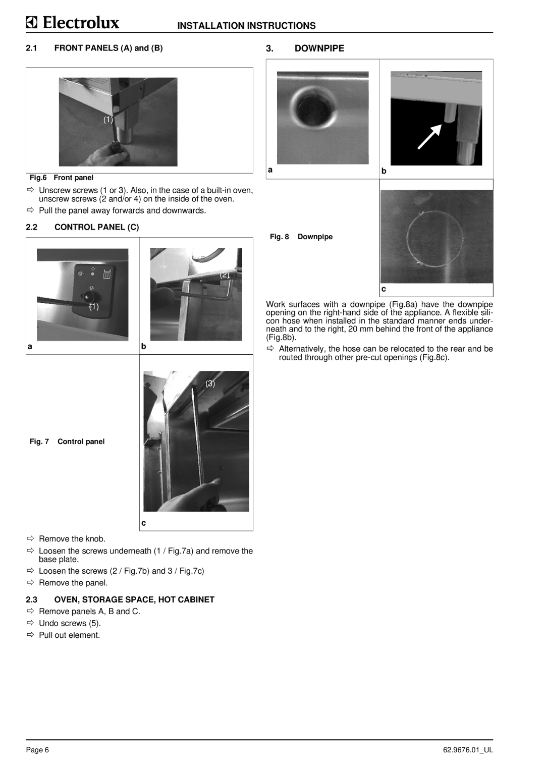
3. | DOWNPIPE |
a | b |
Fig. 8 Downpipe
c
Work surfaces with a downpipe (Fig.8a) have the downpipe opening on the
DAlternatively, the hose can be relocated to the rear and be routed through other
Page 6 | 62.9676.01_UL |