INSTALLATION INSTRUCTIONS
II . INSTALLATION INSTRUCTIONS
1. | INSTALLATION | 1.3 | ASSEMBLING TWO APPLIANCES |
The appliance is designed for connection to fixed lines. The appliances are suitable for setting up as single appliances or as a group of appliances. They can be set up freely in the room, side by side, at the side and/or at the back against a wall.
Gaps between two appliances or appliance and sidewall should be filled with a FDA approved silicone such as Samco RTV103.
1.1DISTANCES
If an appliance is set up next to or against
mm)should be maintained or some form of heat insulation fit-
ted.
The walls must be made up of
1.2HEIGHT ADJUSTMENT
Appliance on feet: Alignment is carried out by screwing the lower foot parts in or out.
Appliance on | Irregularities or differences in height can |
steel plinth: | be equalized by inserting one or several |
| strips of chrome nickel steel. |
Appliance on feet.
DTurn the lower part of the feed to adjust the appliance high.
The feet are adjustable from 4“ to 8“ (100 to 200 mm). A high of 8“ (200 mm) can be recommended and results in an appli- ance high of 35,4“ (900 mm).
Note:
Adjustment of the legs shall provide an unobstructed clearance of minimal 6“ (150 mm) and maximal 8“ (200
mm)beneath the unit due to sanitary and stability aspects.
(1)
(2)
a
(1)
(3)
(2)
b
The lower part of the foot must not be unscrewed too far. The exposure of threads is prohibited.
c
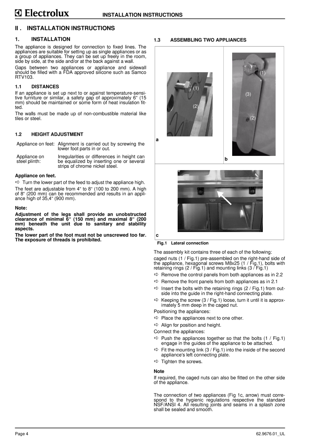
Fig.1 Lateral connection
The assembly kit contains three of each of the following:
caged nuts (1 / Fig.1)
DRemove the control panels from both appliances as in 2.2
DRemove the front panels from both appliances as in 2.1
DInsert the bolts with the retaining rings (2 / Fig.1) from out- side into the guide in the
DKeeping the screw (3 / Fig.1) loose, turn it until it is approx- imately 5 mm deep in the caged nut.
Positioning the appliances:
DPlace the appliances next to one other.
DAlign for position and height.
Connect the appliances:
DPush the appliances together so that the bolts (1 / Fig.1) engage in the guides of the appliance to be attached.
DFit the mounting link (3 / Fig.1) into the inside of the second appliance's left connecting plate.
DTighten the screws.
Note
If required, the caged nuts can also be fitted on the other side of the appliance.
The connection of two appliances (Fig 1c, arrow) must corre- spond to the hygienic regulations respective the standard NSF/ANSI 4. All resulting joints and seams in a splash zone shall be sealed and smooth.
Page 4 | 62.9676.01_UL |