Main Unit Disassembly Process
IMPORTANT:The outside housing and color may vary from the mass produced model.
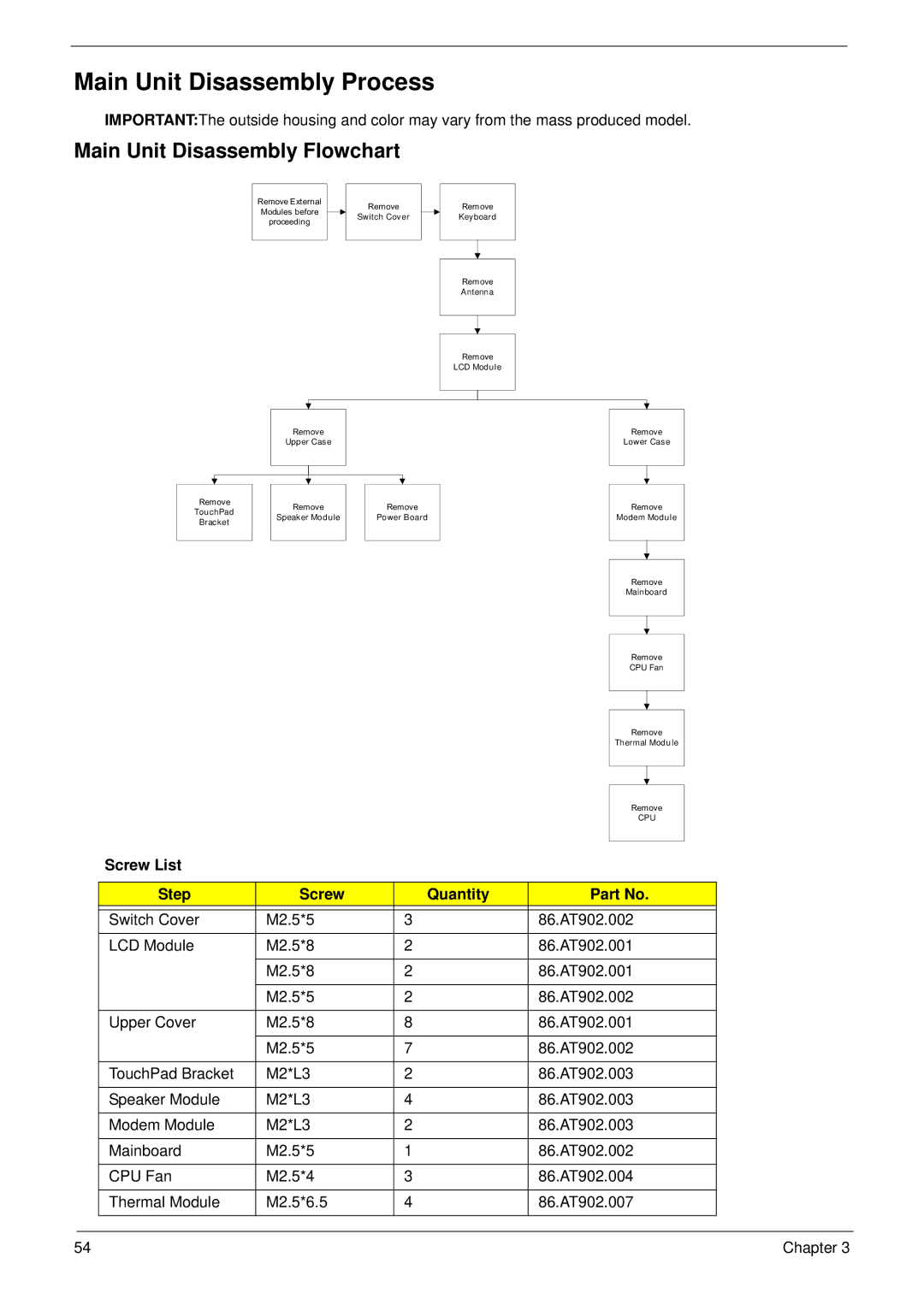
Main Unit Disassembly Flowchart
Remove External Modules before proceeding
Remove
Switch Cover
Remove
Keyboard
Remove
Antenna
Remove
LCD Module
Remove
Upper Case
Remove |
| Remove |
| Remove |
TouchPad |
|
| ||
| Speaker Module |
| Power Board | |
Bracket |
|
| ||
|
|
|
| |
|
|
|
|
|
Remove
Lower Case
Remove
Modem Module
Remove
Mainboard
Remove
CPU Fan
Remove
Thermal Module
Remove
CPU
Screw List
| Step | Screw | Quantity | Part No. |
|
|
|
|
|
|
|
| Switch Cover | M2.5*5 | 3 | 86.AT902.002 |
|
| LCD Module | M2.5*8 | 2 | 86.AT902.001 |
|
|
|
|
|
|
|
|
| M2.5*8 | 2 | 86.AT902.001 |
|
|
|
|
|
|
|
|
| M2.5*5 | 2 | 86.AT902.002 |
|
|
|
|
|
|
|
| Upper Cover | M2.5*8 | 8 | 86.AT902.001 |
|
|
|
|
|
|
|
|
| M2.5*5 | 7 | 86.AT902.002 |
|
|
|
|
|
|
|
| TouchPad Bracket | M2*L3 | 2 | 86.AT902.003 |
|
|
|
|
|
|
|
| Speaker Module | M2*L3 | 4 | 86.AT902.003 |
|
|
|
|
|
|
|
| Modem Module | M2*L3 | 2 | 86.AT902.003 |
|
|
|
|
|
|
|
| Mainboard | M2.5*5 | 1 | 86.AT902.002 |
|
|
|
|
|
|
|
| CPU Fan | M2.5*4 | 3 | 86.AT902.004 |
|
|
|
|
|
|
|
| Thermal Module | M2.5*6.5 | 4 | 86.AT902.007 |
|
|
|
|
|
|
|
|
|
|
|
|
|
54 | Chapter 3 |