CONTROL FEATURES (continued)
Optional Accessory 11BG – SOURCE AVAILABILITY SIGNAL
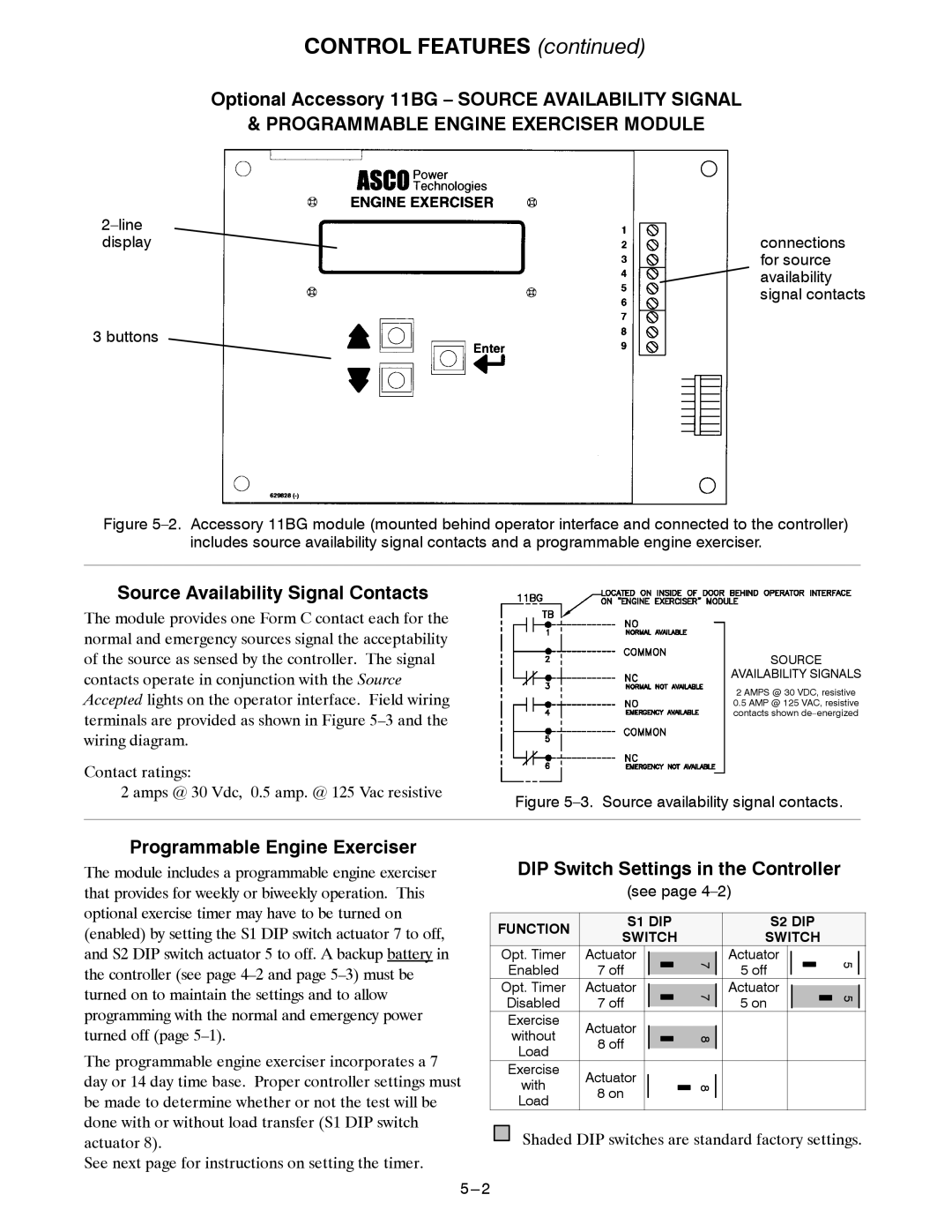
& PROGRAMMABLE ENGINE EXERCISER MODULE
displayconnections for source ![]() availability signal contacts
availability signal contacts
3 buttons
Figure 5–2. Accessory 11BG module (mounted behind operator interface and connected to the controller)
includes source availability signal contacts and a programmable engine exerciser.
Source Availability Signal Contacts
The module provides one Form C contact each for the normal and emergency sources signal the acceptability of the source as sensed by the controller. The signal contacts operate in conjunction with the Source Accepted lights on the operator interface. Field wiring terminals are provided as shown in Figure
Contact ratings:
2 amps @ 30 Vdc, 0.5 amp. @ 125 Vac resistive
SOURCE
AVAILABILITY SIGNALS
2 AMPS @ 30 VDC, resistive
0.5 AMP @ 125 VAC, resistive contacts shown
Figure 5–3. Source availability signal contacts.
Programmable Engine Exerciser
The module includes a programmable engine exerciser that provides for weekly or biweekly operation. This optional exercise timer may have to be turned on (enabled) by setting the S1 DIP switch actuator 7 to off, and S2 DIP switch actuator 5 to off. A backup battery in the controller (see page
The programmable engine exerciser incorporates a 7 day or 14 day time base. Proper controller settings must be made to determine whether or not the test will be done with or without load transfer (S1 DIP switch actuator 8).
See next page for instructions on setting the timer.
DIP Switch Settings in the Controller
(see page 4–2)
FUNCTION | S1 DIP |
|
|
| S2 DIP |
|
| ||||||||||||
SWITCH |
|
|
| SWITCH |
|
| |||||||||||||
|
|
|
|
|
| ||||||||||||||
Opt. Timer | Actuator |
|
|
|
|
|
|
|
| Actuator |
|
|
|
|
|
| 5 |
| |
|
|
|
| 7 |
|
|
|
| |||||||||||
Enabled | 7 off |
|
|
|
|
|
| 5 off |
|
|
|
|
|
|
| ||||
Opt. Timer | Actuator |
|
|
|
|
|
| Actuator |
|
|
|
|
|
| |||||
|
|
|
| 7 |
|
|
|
| 5 |
| |||||||||
Disabled | 7 off |
|
|
|
|
|
|
| 5 on |
|
|
|
|
|
|
| |||
Exercise | Actuator |
|
|
|
|
|
|
|
|
|
|
|
|
|
|
|
|
|
|
without |
|
|
| 8 |
|
|
|
|
|
|
|
|
|
| |||||
Load | 8 off |
|
|
|
|
|
|
|
|
|
|
|
|
|
|
|
|
| |
|
|
|
|
|
|
|
|
|
|
|
|
|
| ||||||
|
|
|
|
|
|
|
|
|
|
|
|
|
|
|
|
|
|
| |
Exercise | Actuator |
|
|
|
|
|
|
|
|
|
|
|
|
|
|
|
|
|
|
with |
|
|
|
| 8 |
|
|
|
|
|
|
|
|
|
| ||||
8 on |
|
|
|
|
|
|
|
|
|
|
|
|
|
|
|
|
| ||
|
|
|
|
|
|
|
|
|
|
|
|
|
|
|
|
| |||
Load |
|
|
|
|
|
|
|
|
|
|
|
|
|
|
| ||||
|
|
|
|
|
|
|
|
|
|
|
|
| |||||||
|
|
|
|
|
|
|
|
|
|
|
|
|
|
|
|
|
|
| |
|
|
|
|
|
|
|
|
|
|
|
|
|
|
|
|
|
|
|
|