SECTION 3 TESTING & SERVICE
PREVENTIVE MAINTENANCE
For high reliability and long life for the ATS:
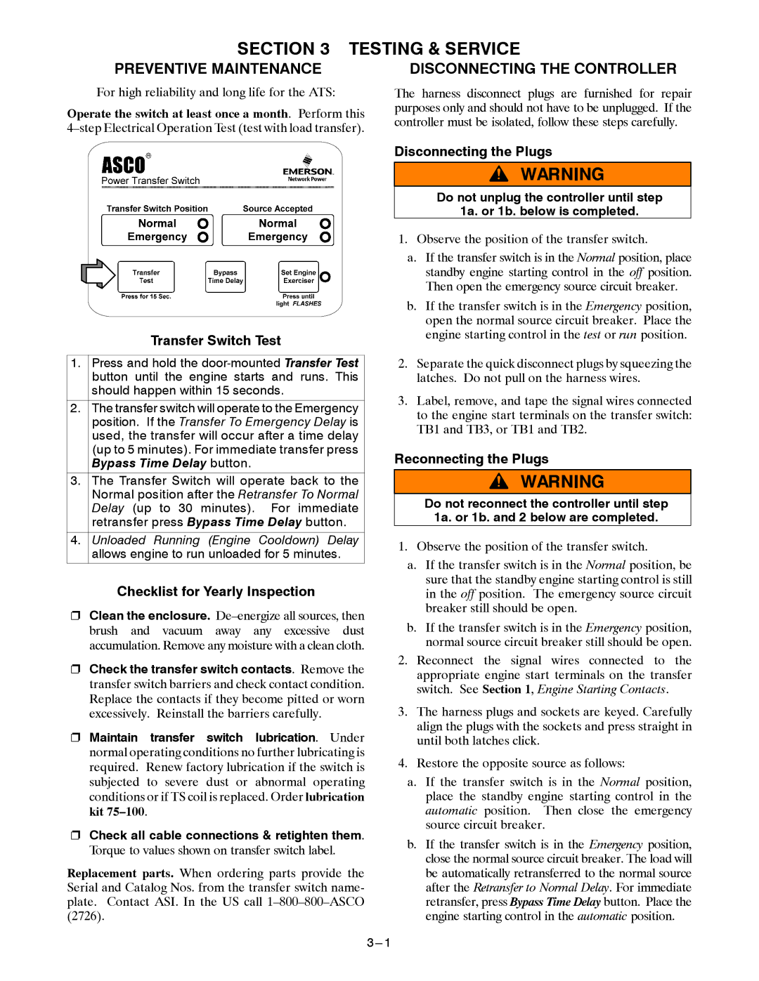
Operate the switch at least once a month. Perform this
DISCONNECTING THE CONTROLLER
The harness disconnect plugs are furnished for repair purposes only and should not have to be unplugged. If the controller must be isolated, follow these steps carefully.
Transfer Switch Test
1.Press and hold the
2.The transfer switch will operate to the Emergency position. If the Transfer To Emergency Delay is used, the transfer will occur after a time delay (up to 5 minutes). For immediate transfer press Bypass Time Delay button.
3.The Transfer Switch will operate back to the Normal position after the Retransfer To Normal Delay (up to 30 minutes). For immediate retransfer press Bypass Time Delay button.
4.Unloaded Running (Engine Cooldown) Delay allows engine to run unloaded for 5 minutes.
Checklist for Yearly Inspection
SClean the enclosure.
SCheck the transfer switch contacts. Remove the transfer switch barriers and check contact condition. Replace the contacts if they become pitted or worn excessively. Reinstall the barriers carefully.
SMaintain transfer switch lubrication. Under normal operating conditions no further lubricating is required. Renew factory lubrication if the switch is subjected to severe dust or abnormal operating conditions or if TS coil is replaced. Order lubrication kit
SCheck all cable connections & retighten them. Torque to values shown on transfer switch label.
Replacement parts. When ordering parts provide the Serial and Catalog Nos. from the transfer switch name- plate. Contact ASI. In the US call
Disconnecting the Plugs
Do not unplug the controller until step
1a. or 1b. below is completed.
1.Observe the position of the transfer switch.
a.If the transfer switch is in the Normal position, place standby engine starting control in the off position. Then open the emergency source circuit breaker.
b.If the transfer switch is in the Emergency position, open the normal source circuit breaker. Place the engine starting control in the test or run position.
2.Separate the quick disconnect plugs by squeezing the latches. Do not pull on the harness wires.
3.Label, remove, and tape the signal wires connected to the engine start terminals on the transfer switch: TB1 and TB3, or TB1 and TB2.
Reconnecting the Plugs
Do not reconnect the controller until step 1a. or 1b. and 2 below are completed.
1.Observe the position of the transfer switch.
a.If the transfer switch is in the Normal position, be sure that the standby engine starting control is still in the off position. The emergency source circuit breaker still should be open.
b.If the transfer switch is in the Emergency position, normal source circuit breaker still should be open.
2.Reconnect the signal wires connected to the appropriate engine start terminals on the transfer switch. See Section 1, Engine Starting Contacts.
3.The harness plugs and sockets are keyed. Carefully align the plugs with the sockets and press straight in until both latches click.
4.Restore the opposite source as follows:
a.If the transfer switch is in the Normal position, place the standby engine starting control in the automatic position. Then close the emergency source circuit breaker.
b.If the transfer switch is in the Emergency position, close the normal source circuit breaker. The load will be automatically retransferred to the normal source after the Retransfer to Normal Delay. For immediate retransfer, press Bypass Time Delay button. Place the engine starting control in the automatic position.