Connectivity Module | Troubleshooting |
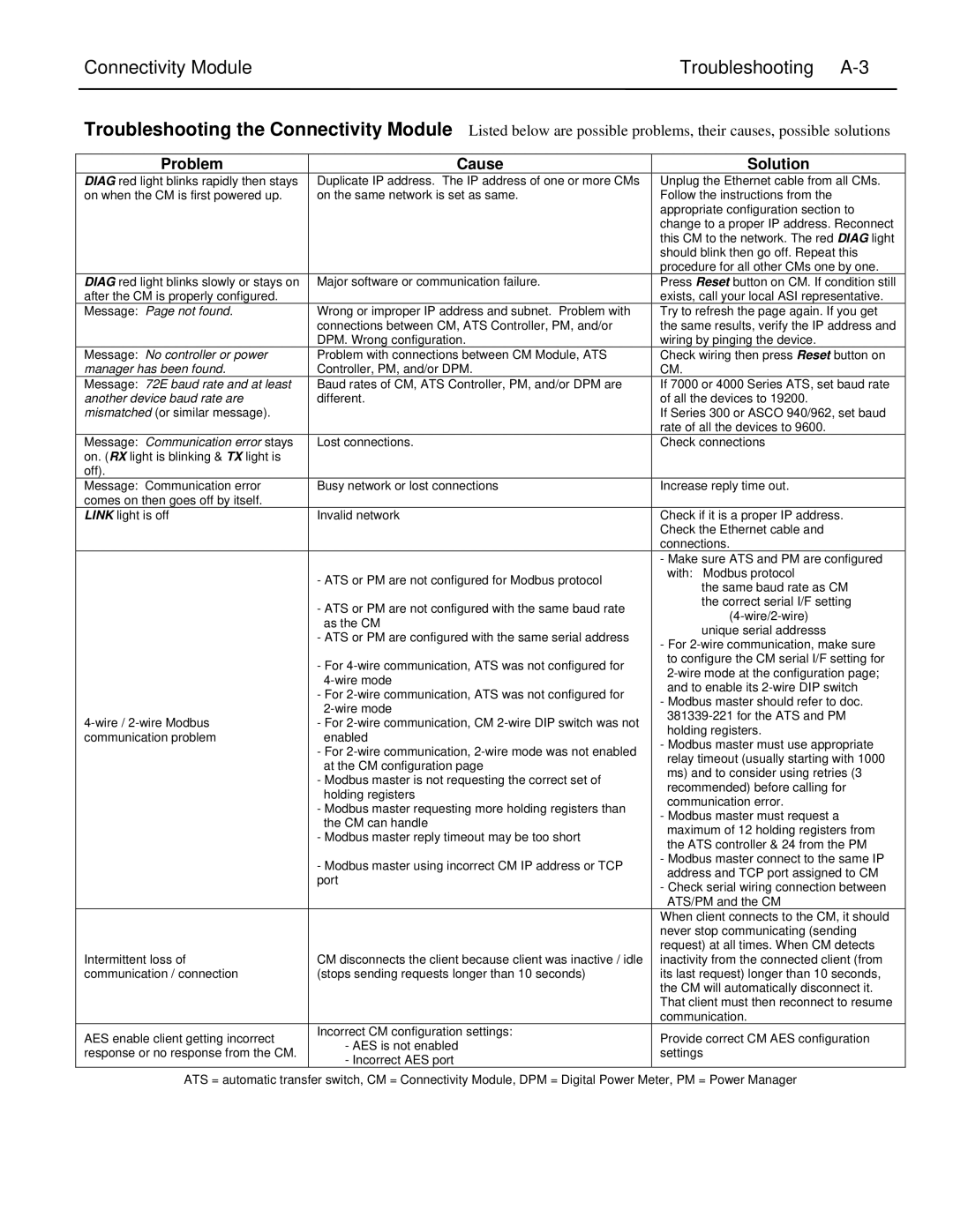
Troubleshooting the Connectivity Module Listed below are possible problems, their causes, possible solutions
Problem | Cause | |
DIAG red light blinks rapidly then stays | Duplicate IP address. The IP address of one or more CMs | |
on when the CM is first powered up. | on the same network is set as same. | |
|
| |
DIAG red light blinks slowly or stays on | Major software or communication failure. | |
after the CM is properly configured. |
| |
Message: Page not found. | Wrong or improper IP address and subnet. Problem with | |
| connections between CM, ATS Controller, PM, and/or | |
| DPM. Wrong configuration. | |
Message: No controller or power | Problem with connections between CM Module, ATS | |
manager has been found. | Controller, PM, and/or DPM. | |
Message: 72E baud rate and at least | Baud rates of CM, ATS Controller, PM, and/or DPM are | |
another device baud rate are | different. | |
mismatched (or similar message). |
| |
|
| |
Message: Communication error stays | Lost connections. | |
on. (RX light is blinking & TX light is |
| |
off). |
| |
Message: Communication error | Busy network or lost connections | |
comes on then goes off by itself. |
| |
LINK light is off | Invalid network | |
|
| |
| - ATS or PM are not configured for Modbus protocol | |
| - ATS or PM are not configured with the same baud rate | |
| as the CM | |
| - ATS or PM are configured with the same serial address | |
| - For | |
| ||
| - For | |
- For | ||
communication problem | enabled | |
| - For | |
| at the CM configuration page | |
| - Modbus master is not requesting the correct set of | |
| holding registers | |
| - Modbus master requesting more holding registers than | |
| the CM can handle | |
| - Modbus master reply timeout may be too short | |
| - Modbus master using incorrect CM IP address or TCP | |
| port | |
|
| |
Intermittent loss of | CM disconnects the client because client was inactive / idle | |
communication / connection | (stops sending requests longer than 10 seconds) | |
|
| |
AES enable client getting incorrect | Incorrect CM configuration settings: | |
- AES is not enabled | ||
response or no response from the CM. | ||
- Incorrect AES port | ||
|
Solution
Unplug the Ethernet cable from all CMs. Follow the instructions from the appropriate configuration section to change to a proper IP address. Reconnect this CM to the network. The red DIAG light should blink then go off. Repeat this procedure for all other CMs one by one. Press Reset button on CM. If condition still exists, call your local ASI representative. Try to refresh the page again. If you get the same results, verify the IP address and wiring by pinging the device.
Check wiring then press Reset button on CM.
If 7000 or 4000 Series ATS, set baud rate of all the devices to 19200.
If Series 300 or ASCO 940/962, set baud rate of all the devices to 9600.
Check connections
Increase reply time out.
Check if it is a proper IP address. Check the Ethernet cable and connections.
-Make sure ATS and PM are configured with: Modbus protocol
the same baud rate as CM the correct serial I/F setting
-For
-Modbus master should refer to doc.
-Modbus master must use appropriate relay timeout (usually starting with 1000 ms) and to consider using retries (3 recommended) before calling for communication error.
-Modbus master must request a maximum of 12 holding registers from the ATS controller & 24 from the PM
-Modbus master connect to the same IP address and TCP port assigned to CM
-Check serial wiring connection between ATS/PM and the CM
When client connects to the CM, it should never stop communicating (sending request) at all times. When CM detects inactivity from the connected client (from its last request) longer than 10 seconds, the CM will automatically disconnect it. That client must then reconnect to resume communication.
Provide correct CM AES configuration settings
ATS = automatic transfer switch, CM = Connectivity Module, DPM = Digital Power Meter, PM = Power Manager