ii Welcome | Connectivity Module |
Who Should Use this Installation Manual
This manual for the Connectivity Module should be used to assist individuals who will:
|
| • install the Connectivity Module (mount and wire) | ||
|
| • configure the Connectivity Module |
| |
|
| • enter in information about your Automatic Transfer Switches | ||
|
| (7000 & 4000 Series, Series 300, ASCO 940,962,436,434,447,448) | ||
|
| • use Ethernet access to monitor Connectivity Module (connected devices) | ||
Prerequisites | A working knowledge of Windows XP ® and Windows Internet Explorer 6.0 or higher | |||
|
| (with Microsoft Virtual Machine or the latest version of the Java Runtime Environment | ||
|
| loaded) is necessary to configure the Connectivity Module. | ||
Important information | To properly set up the software, you will need the nameplate data and other | |||
that you will need |
| information from all your Automatic Transfer Switches including: | ||
|
| • ATS Name (your designation for the ATS) | ||
|
| • ATS Location (where the ATS is located in the building) | ||
|
| • Voltage Rating, Ampere Rating, and number of Poles for each ATS | ||
|
| • Catalog No. and Serial No. of each ATS | ||
|
| • Type of ATS (ATS or ATS/BP [ATS with | ||
|
| • Device Address (set in each ATS, Power Manager , or Digital Power Meter) | ||
|
|
|
|
|
|
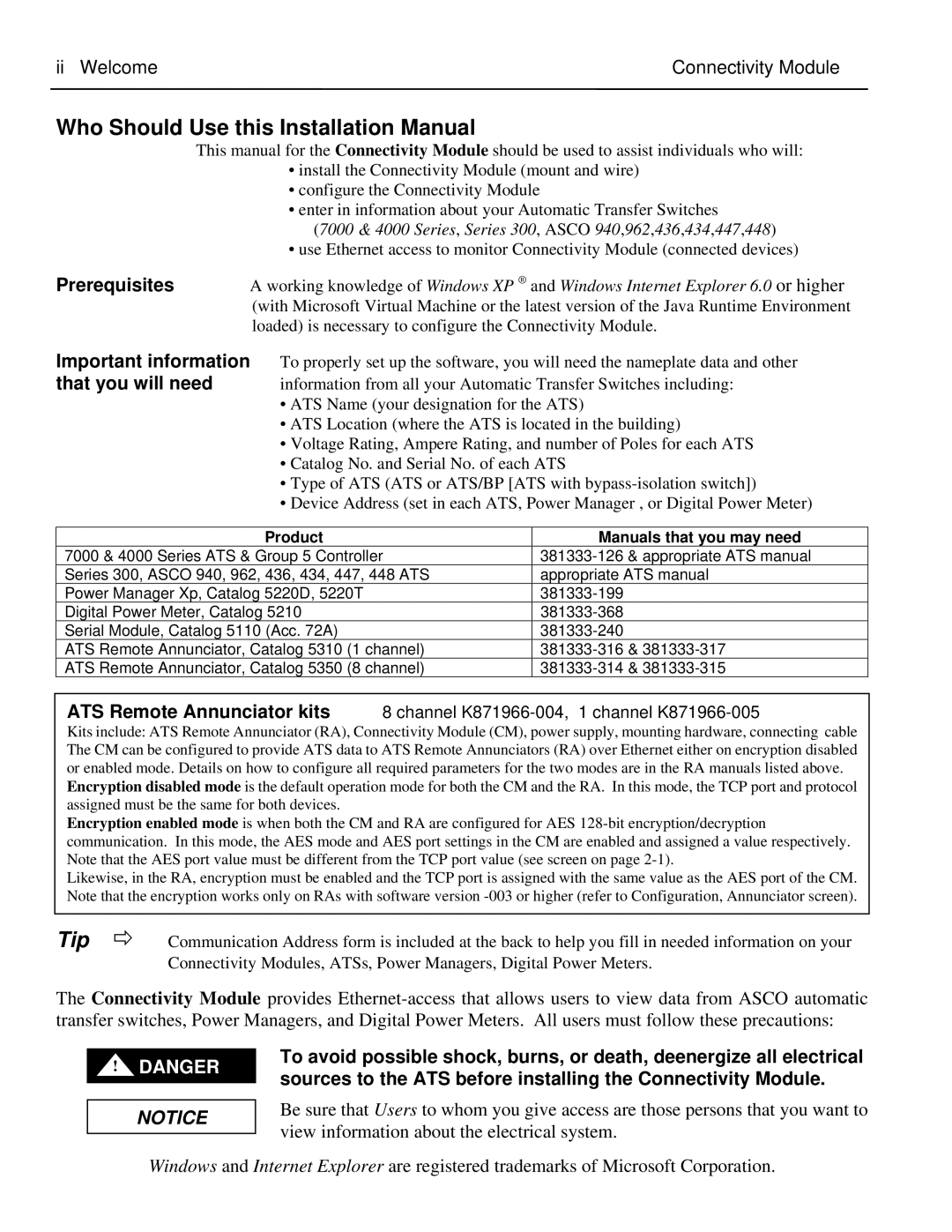
| Product |
| Manuals that you may need |
7000 & 4000 Series ATS & Group 5 Controller |
| |||
Series 300, ASCO 940, 962, 436, 434, 447, 448 ATS |
| appropriate ATS manual | ||
Power Manager Xp, Catalog 5220D, 5220T |
| |||
Digital Power Meter, Catalog 5210 |
| |||
Serial Module, Catalog 5110 (Acc. 72A) |
| |||
ATS Remote Annunciator, Catalog 5310 (1 channel) |
| |||
ATS Remote Annunciator, Catalog 5350 (8 channel) |
| |||
ATS Remote Annunciator kits 8 channel
Kits include: ATS Remote Annunciator (RA), Connectivity Module (CM), power supply, mounting hardware, connecting cable The CM can be configured to provide ATS data to ATS Remote Annunciators (RA) over Ethernet either on encryption disabled or enabled mode. Details on how to configure all required parameters for the two modes are in the RA manuals listed above.
Encryption disabled mode is the default operation mode for both the CM and the RA. In this mode, the TCP port and protocol assigned must be the same for both devices.
Encryption enabled mode is when both the CM and RA are configured for AES
Likewise, in the RA, encryption must be enabled and the TCP port is assigned with the same value as the AES port of the CM. Note that the encryption works only on RAs with software version
Tip Ö | Communication Address form is included at the back to help you fill in needed information on your |
| Connectivity Modules, ATSs, Power Managers, Digital Power Meters. |
The Connectivity Module provides
!DANGER
NOTICE
To avoid possible shock, burns, or death, deenergize all electrical sources to the ATS before installing the Connectivity Module.
Be sure that Users to whom you give access are those persons that you want to view information about the electrical system.
Windows and Internet Explorer are registered trademarks of Microsoft Corporation.
