Reference Manual

00809-0100-4697, Rev EA October 2011

Rosemount 848T

Index

Numerics

2-Inch Pipe Stand

Mounting . . . . . . . . . . . . .2-3

A

Alarms

Configuration . . . . . . . . . .3-3

Analog Input

Configuration . . . . . . . . . .3-6

Ground . . . . . . . . . . . . . .2-9

Analog Input Function Block . . D-1

Advanced Features . . . . D-7

Alarm Detection . . . . . . . D-6

Application Information . . D-8

Block Errors . . . . . . . . . . D-5

Configuration . . . . . . . . . .3-6

Direct . . . . . . . . . . . . . . D-4

Filtering . . . . . . . . . . . . . D-4

Functionality . . . . . . . . . D-3

Indirect . . . . . . . . . . . . . D-4

Indirect Square Root . . . . D-5

Modes . . . . . . . . . . . . . . D-6

Automatic . . . . . . . . D-6

Manual . . . . . . . . . . D-6

Out of Service . . . . . D-6

Parameters . . . . . . . . . . D-1

Signal Conversion . . . . . D-4

Simulation . . . . . . . . . . . D-3

Status Handling . . . . . . . D-7

Troubleshooting . . . . . . . D-8

Wiring Diagram . . . . . . . .2-6

B

Block Operation . . . . . . . . . . C-3

Alerts . . . . . . . . . . . . . . C-3

Instrument Specific Blocks C-3

C

Cable Glands

Installation . . . . . . . . . . .2-12

Commissioning . . . . . . . . . . . .4-2

Tag . . . . . . . . . . . . . . . . 2-11

Conduit Entries . . . . . . . . . . .2-12

Configuration . . . . . . . . . . . . . 3-2

Alarms . . . . . . . . . . . . . . 3-3

Analog Transmitters . . . . . 3-6

Analog Input Block . . 3-6

Multiple Analog Input Block

3-6

Block . . . . . . . . . . . . . . . 3-7

Custom . . . . . . . . . . . . . . 3-2

Damping . . . . . . . . . . . . . 3-3

Differential Sensor Blocks . 3-3

Methods . . . . . . . . . . . . . 3-2

Monitoring Applications

Single Selection . . . . 3-4

Typical . . . . . . . . . . . 3-4Reset . . . . . . . . . . . . . . . 4-3Restart Processor . . . 4-3Restart with Defaults . 4-3Resource Block . . . . . . . . 3-7Standard . . . . . . . . . . . . . 3-2Transmitter . . . . . . . . . . . 3-2

Connections . . . . . . . . . . . . . 2-4Analog Inputs . . . . . . . . . 2-5Millivolt Inputs . . . . . . . . . 2-5Ohm Inputs . . . . . . . . . . . 2-5Power Supply . . . . . . . . . 2-7RTD Inputs . . . . . . . . . . . 2-5Thermocouple Inputs . . . . 2-5

D

Damping

Configuration . . . . . . . . . . 3-3

Device Descriptions . . . . . . . .C-3

Differential Sensor Blocks

Configuration . . . . . . . . . . 3-3

Differential Transducer Block

Troubleshooting . . . . . . . . 4-4

DIN Rail

Mounting . . . . . . . . . . . . 2-2

Drawing

Switch Location . . . . . . . 2-10

Drawings

848T Analog Connector . . 2-6

Analog Input Wiring . . . . . 2-6

Block Diagram . . . . . . . . . 4-2

Block Internal Structure . .C-2

Cable Gland Installation . 2-12

Commissioning Tag . . . . 2-11

Conduit Entries Installation 2-12

Installation . . . . . . . . . .B-10

Sensor Wiring . . . . . . . . . 2-4

Transmitter Label . . . . . . . 2-7

Transmitter Wiring . . . . . . 2-4

F

FOUNDATION Fieldbus . . . . . . . 4-1

Addressing . . . . . . . . . . . C-6

Block Operation . . . . . . . C-3

Alerts . . . . . . . . . . . C-3

Instrument- Specific Blocks

C-3

Check . . . . . . . . . . . . . . 4-3

Device Descriptions . . . . . C-3

Function Block Scheduling C-8

Function Blocks . . . . . . . C-1

Link Active Scheduler . . . C-4

Network Communication . C-4

Overview . . . . . . . . . . . . C-1

Scheduled Transfers . . . . C-6

Troubleshooting . . . . . . . 4-4

Unscheduled Transfers . . C-7

Function Blocks . . . . . . . . . . . C-1

Analog Input . . . . . . . . . . D-1

Input Selector Function Block .

D-15

Multiple Analog Input . . . . D-9

Scheduling . . . . . . . . . . . C-8

G

Grounding . . . . . . . . . . . . . . . 2-8

Analog Device . . . . . . . . 2-9

Grounded Thermocouple . 2-9

Shielded Wire . . . . . . . . . 2-8

Transmitter Enclosure . . . 2-9

Ungrounded mV . . . . . . . 2-8

Ungrounded RTD/Ohm . . 2-8

Ungrounded Thermocouple 2-8

H

Hardware

Maintenance . . . . . . . . . . 4-3

Communication Check 4-3

Power Check . . . . . . 4-3

Reset Configuration . 4-3

Sensor Check . . . . . 4-3

I

Input Selector Function Block D-15

Alarm Detection . . . . . . D-18

Application Information . D-19

Block Execution . . . . . . D-19

Errors . . . . . . . . . . . . . D-17

Functionality . . . . . . . . . D-17

Index-1

Page 111
Image 111
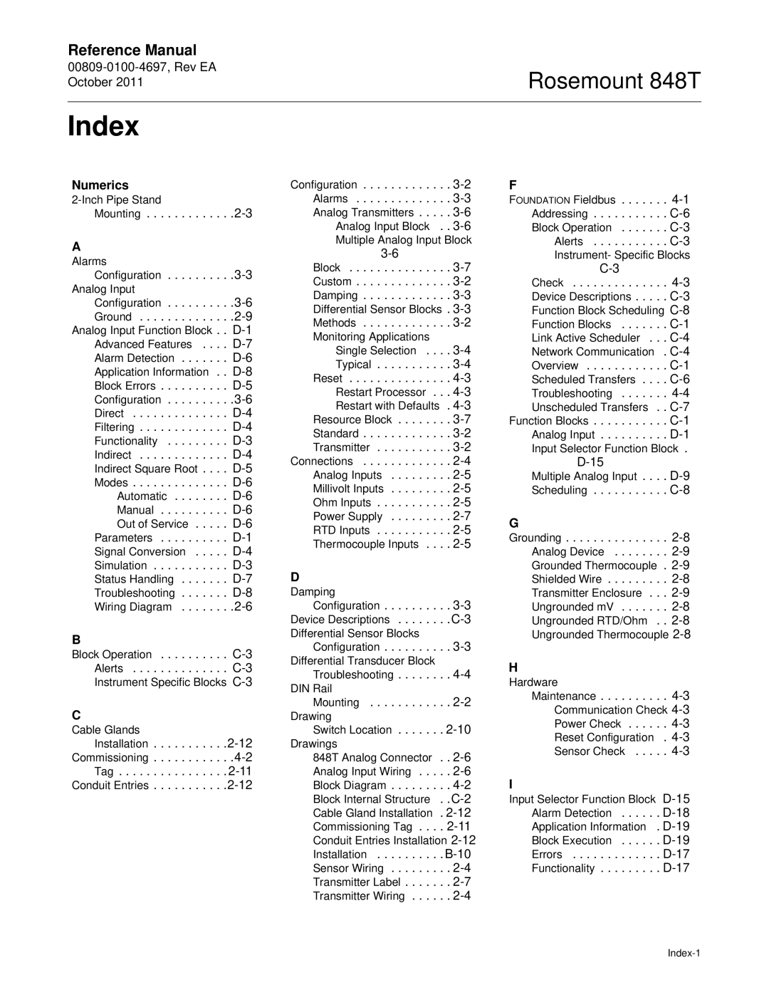
Emerson 848T manual Index, Numerics

848T specifications

The Emerson 848T is a state-of-the-art temperature transmitter designed for accurate and reliable temperature measurement in various industrial applications. This device has gained recognition for its advanced features and robust performance, making it a popular choice among engineers and technicians in the field.

One of the key highlights of the Emerson 848T is its unique dual-channel capability, which allows it to seamlessly monitor two temperature sources simultaneously. This functionality is particularly beneficial in processes where multiple temperature points need to be assessed, optimizing efficiency and reducing the need for additional equipment. It supports various sensor types, including thermocouples, RTDs, and resistance temperature detectors, making it versatile for different applications.

The 848T is equipped with sophisticated digital processing technology, which enhances its accuracy and stability. It features a 24-bit analog-to-digital converter, ensuring precise measurement and minimizing drift over time. Moreover, the device boasts a wide operating temperature range, accommodating ambient conditions from -40°C to 85°C. This durability makes it suitable for harsh environments commonly encountered in industries such as oil and gas, pharmaceuticals, and power generation.

Another significant characteristic of the Emerson 848T is its configurable output options. Users can choose from a range of output signals, including 4-20 mA, which provides a standard interface for integration into existing control systems. Additionally, it offers a HART communication protocol, allowing for easy configuration, calibration, and diagnostics through a digital interface. This feature enhances the transmitter's usability, enabling operators to perform adjustments without direct access to the device.

The device is designed with user-friendliness in mind. Its intuitive setup procedure and robust graphical user interface simplify the commissioning process, ensuring that even those new to the technology can easily navigate the system. An integrated LCD display provides real-time readings and status information, facilitating monitoring at a glance.

In summary, the Emerson 848T temperature transmitter combines reliable performance, user-friendly design, and advanced digital technologies. Its dual-channel capability, wide sensor compatibility, and adjustable output options make it an essential tool for achieving precise temperature measurements in various industrial settings. With these compelling features, the Emerson 848T stands out as a leading choice for professionals seeking accuracy and efficiency in their temperature monitoring applications.