Rosemount 848T

Reference Manual

00809-0100-4697, Rev EA October 2011

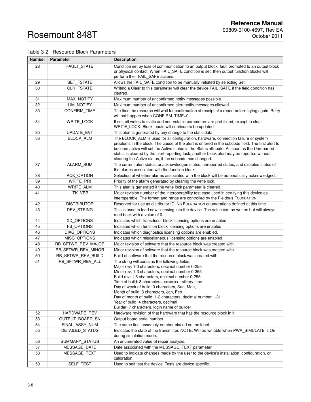
Table 3-2. Resource Block Parameters

Number

Parameter

Description

28

FAULT_STATE

Condition set by loss of communication to an output block, fault promoted to an output block


or physical contact. When FAIL_SAFE condition is set, then output function blocks will


perform their FAIL_SAFE actions.

29

SET_FSTATE

Allows the FAIL_SAFE condition to be manually initiated by selecting Set.

30

CLR_FSTATE

Writing a Clear to this parameter will clear the device FAIL_SAFE if the field condition has


cleared.

31

MAX_NOTIFY

Maximum number of unconfirmed notify messages possible.

32

LIM_NOTIFY

Maximum number of unconfirmed alert notify messages allowed.

33

CONFIRM_TIME

The time the resource will wait for confirmation of receipt of a report before trying again. Retry


will not happen when CONFIRM_TIME=0.

34

WRITE_LOCK

If set, all writes to static and non-volatile parameters are prohibited, except to clear


WRITE_LOCK. Block inputs will continue to be updated.

35

UPDATE_EVT

This alert is generated by any change to the static data.

36

BLOCK_ALM

The BLOCK_ALM is used for all configuration, hardware, connection failure or system


problems in the block. The cause of the alert is entered in the subcode field. The first alert to


become active will set the Active status in the Status attribute. As soon as the Unreported


status is cleared by the alert reporting task, another block alert may be reported without


clearing the Active status, if the subcode has changed.

37

ALARM_SUM

The current alert status, unacknowledged states, unreported states, and disabled states of


the alarms associated with the function block.

38

ACK_OPTION

Selection of whether alarms associated with the block will be automatically acknowledged.

39

WRITE_PRI

Priority of the alarm generated by clearing the write lock.

40

WRITE_ALM

This alert is generated if the write lock parameter is cleared.

41

ITK_VER

Major revision number of the interoperability test case used in certifying this device as


interoperable. The format and range are controlled by the Fieldbus FOUNDATION.

42

DISTRIBUTOR

Reserved for use as distributor ID. No FOUNDATION enumerations defined at this time.

43

DEV_STRING

This is used to load new licensing into the device. The value can be written but will always


read back with a value of 0.

44

XD_OPTIONS

Indicates which transducer block licensing options are enabled.

45

FB_OPTIONS

Indicates which function block licensing options are enabled.

46

DIAG_OPTIONS

Indicates which diagnostics licensing options are enabled.

47

MISC_OPTIONS

Indicates which miscellaneous licensing options are enabled.

48

RB_SFTWR_REV_MAJOR

Major revision of software that the resource block was created with.

49

RB_SFTWR_REV_MINOR

Minor revision of software that the resource block was created with.

50

RB_SFTWR_REV_BUILD

Build of software that the resource block was created with.

51

RB_SFTWR_REV_ALL

The string will contains the following fields:


Major rev: 1-3 characters, decimal number 0-255


Minor rev: 1-3 characters, decimal number 0-255


Build rev: 1-5 characters, decimal number 0-255


Time of build: 8 characters, xx:xx:xx, military time


Day of week of build: 3 characters, Sun, Mon, …


Month of build: 3 characters, Jan, Feb.


Day of month of build: 1-2 characters, decimal number 1-31


Year of build: 4 characters, decimal


Builder: 7 characters, login name of builder

52

HARDWARE_REV

Hardware revision of that hardware that has the resource block in it.

53

OUTPUT_BOARD_SN

Output board serial number.

54

FINAL_ASSY_NUM

The same final assembly number placed on the label.

55

DETAILED_STATUS

Indicates the state of the transmitter. NOTE: Will be writable when PWA_SIMULATE is On


during simulation mode.

56

SUMMARY_STATUS

An enumerated value of repair analysis.

57

MESSAGE_DATE

Date associated with the MESSAGE_TEXT parameter

58

MESSAGE_TEXT

Used to indicate changes made by the user to the device’s installation, configuration, or


calibration.

59

SELF_TEST

Used to self test the device. Tests are device specific.

3-8

Page 30
Image 30
Emerson 848T manual 00809-0100-4697, Rev EA October Resource Block Parameters

848T specifications

The Emerson 848T is a state-of-the-art temperature transmitter designed for accurate and reliable temperature measurement in various industrial applications. This device has gained recognition for its advanced features and robust performance, making it a popular choice among engineers and technicians in the field.

One of the key highlights of the Emerson 848T is its unique dual-channel capability, which allows it to seamlessly monitor two temperature sources simultaneously. This functionality is particularly beneficial in processes where multiple temperature points need to be assessed, optimizing efficiency and reducing the need for additional equipment. It supports various sensor types, including thermocouples, RTDs, and resistance temperature detectors, making it versatile for different applications.

The 848T is equipped with sophisticated digital processing technology, which enhances its accuracy and stability. It features a 24-bit analog-to-digital converter, ensuring precise measurement and minimizing drift over time. Moreover, the device boasts a wide operating temperature range, accommodating ambient conditions from -40°C to 85°C. This durability makes it suitable for harsh environments commonly encountered in industries such as oil and gas, pharmaceuticals, and power generation.

Another significant characteristic of the Emerson 848T is its configurable output options. Users can choose from a range of output signals, including 4-20 mA, which provides a standard interface for integration into existing control systems. Additionally, it offers a HART communication protocol, allowing for easy configuration, calibration, and diagnostics through a digital interface. This feature enhances the transmitter's usability, enabling operators to perform adjustments without direct access to the device.

The device is designed with user-friendliness in mind. Its intuitive setup procedure and robust graphical user interface simplify the commissioning process, ensuring that even those new to the technology can easily navigate the system. An integrated LCD display provides real-time readings and status information, facilitating monitoring at a glance.

In summary, the Emerson 848T temperature transmitter combines reliable performance, user-friendly design, and advanced digital technologies. Its dual-channel capability, wide sensor compatibility, and adjustable output options make it an essential tool for achieving precise temperature measurements in various industrial settings. With these compelling features, the Emerson 848T stands out as a leading choice for professionals seeking accuracy and efficiency in their temperature monitoring applications.