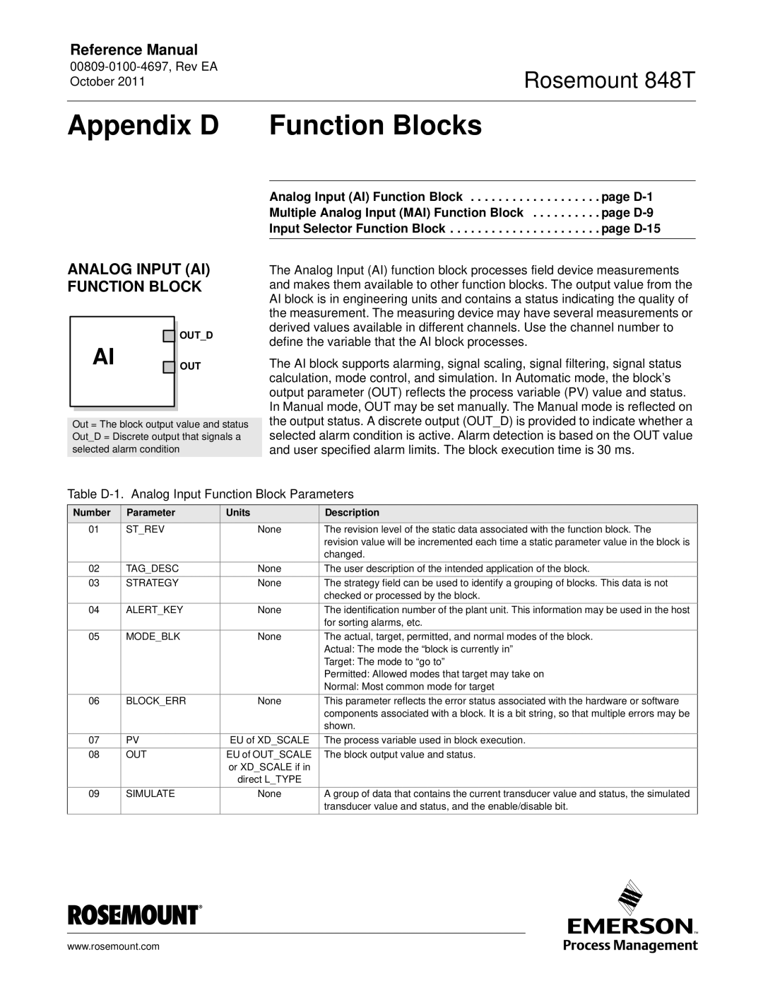
848T specifications
The Emerson 848T is a state-of-the-art temperature transmitter designed for accurate and reliable temperature measurement in various industrial applications. This device has gained recognition for its advanced features and robust performance, making it a popular choice among engineers and technicians in the field.One of the key highlights of the Emerson 848T is its unique dual-channel capability, which allows it to seamlessly monitor two temperature sources simultaneously. This functionality is particularly beneficial in processes where multiple temperature points need to be assessed, optimizing efficiency and reducing the need for additional equipment. It supports various sensor types, including thermocouples, RTDs, and resistance temperature detectors, making it versatile for different applications.
The 848T is equipped with sophisticated digital processing technology, which enhances its accuracy and stability. It features a 24-bit analog-to-digital converter, ensuring precise measurement and minimizing drift over time. Moreover, the device boasts a wide operating temperature range, accommodating ambient conditions from -40°C to 85°C. This durability makes it suitable for harsh environments commonly encountered in industries such as oil and gas, pharmaceuticals, and power generation.
Another significant characteristic of the Emerson 848T is its configurable output options. Users can choose from a range of output signals, including 4-20 mA, which provides a standard interface for integration into existing control systems. Additionally, it offers a HART communication protocol, allowing for easy configuration, calibration, and diagnostics through a digital interface. This feature enhances the transmitter's usability, enabling operators to perform adjustments without direct access to the device.
The device is designed with user-friendliness in mind. Its intuitive setup procedure and robust graphical user interface simplify the commissioning process, ensuring that even those new to the technology can easily navigate the system. An integrated LCD display provides real-time readings and status information, facilitating monitoring at a glance.
In summary, the Emerson 848T temperature transmitter combines reliable performance, user-friendly design, and advanced digital technologies. Its dual-channel capability, wide sensor compatibility, and adjustable output options make it an essential tool for achieving precise temperature measurements in various industrial settings. With these compelling features, the Emerson 848T stands out as a leading choice for professionals seeking accuracy and efficiency in their temperature monitoring applications.

