Reference Manual

00809-0100-4697, Rev EA October 2011

Rosemount 848T

There may be many LM devices on a segment but only the LAS is actively controlling communication traffic. The remaining LM devices on the segment are in a stand-by state, ready to take over if the primary LAS fails. This is achieved by constantly monitoring the communication traffic on the bus and determining if activity is not present. Since there can be multiple LM devices on the segment when the primary LAS fails, the device with the lowest node address will become the primary LAS and take control of the bus. Using this strategy, multiple LAS failures can be handled with no loss of the LAS capability of the communications bus.

LAS Parameters

There are many bus communication parameters but only a few are used. For standard RS-232 communications, the configuration parameters are baud rate, start / stop bits, and parity. The key parameters for H1 FOUNDATION fieldbus are as follows.

Slot Time (ST) – Used during the bus master election process. It is the maximum amount of time permitted for device A to send a message to device B. Slot time is a parameter which defines a worst case delay which includes internal delay in the sending device and the receiving device. Increasing the value of ST slows down bus traffic because a LAS device must wait longer prior to determining that the LM is down.

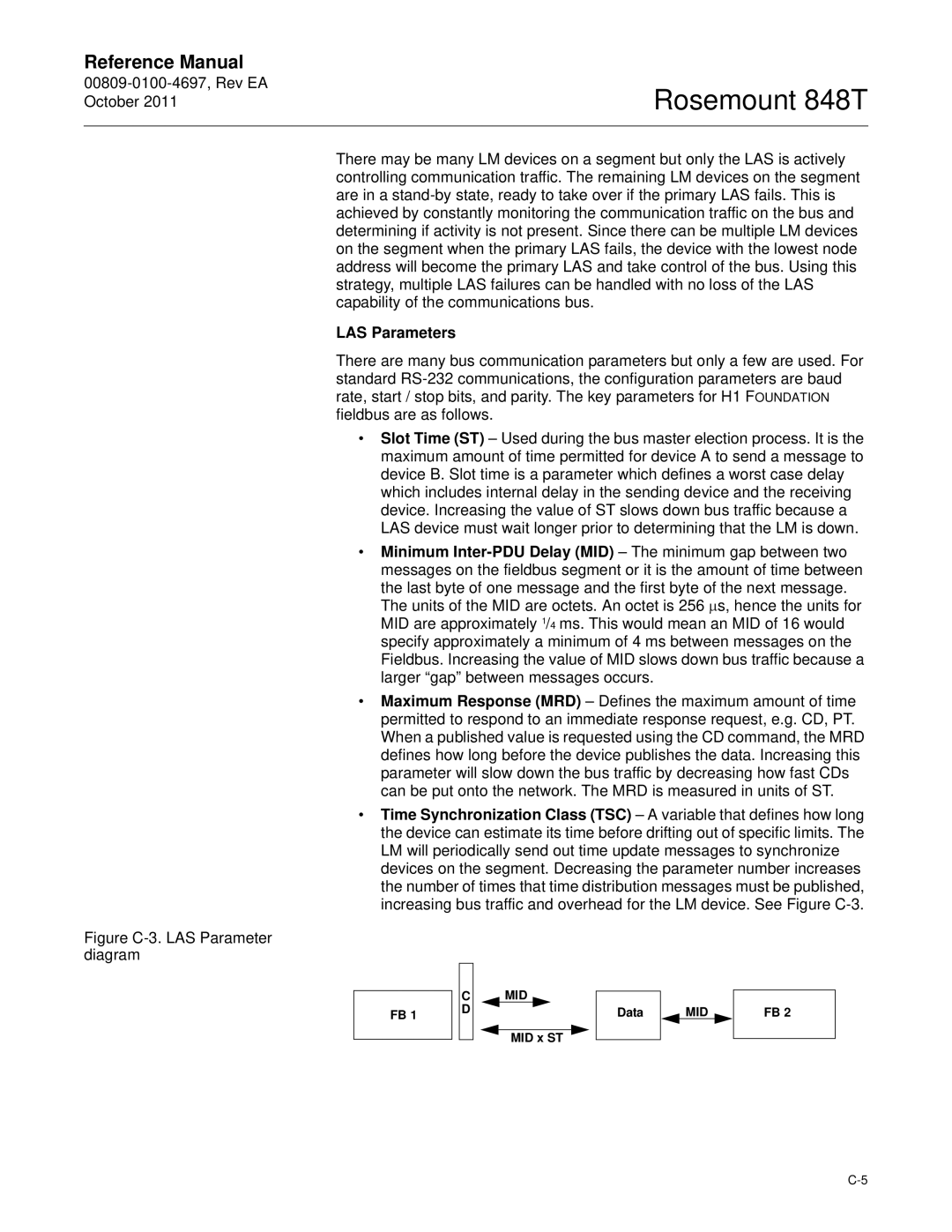
Minimum Inter-PDU Delay (MID) – The minimum gap between two messages on the fieldbus segment or it is the amount of time between the last byte of one message and the first byte of the next message. The units of the MID are octets. An octet is 256 μs, hence the units for MID are approximately 1/4 ms. This would mean an MID of 16 would specify approximately a minimum of 4 ms between messages on the Fieldbus. Increasing the value of MID slows down bus traffic because a larger “gap” between messages occurs.

Maximum Response (MRD) – Defines the maximum amount of time permitted to respond to an immediate response request, e.g. CD, PT. When a published value is requested using the CD command, the MRD defines how long before the device publishes the data. Increasing this parameter will slow down the bus traffic by decreasing how fast CDs can be put onto the network. The MRD is measured in units of ST.

Time Synchronization Class (TSC) – A variable that defines how long the device can estimate its time before drifting out of specific limits. The LM will periodically send out time update messages to synchronize devices on the segment. Decreasing the parameter number increases the number of times that time distribution messages must be published, increasing bus traffic and overhead for the LM device. See Figure C-3.

Figure C-3. LAS Parameter diagram

FB 1

C D

MID

MID x ST

Data

MID

FB 2

C-5

Page 87
Image 87
Emerson 848T manual LAS Parameters, MID x ST Data

848T specifications

The Emerson 848T is a state-of-the-art temperature transmitter designed for accurate and reliable temperature measurement in various industrial applications. This device has gained recognition for its advanced features and robust performance, making it a popular choice among engineers and technicians in the field.

One of the key highlights of the Emerson 848T is its unique dual-channel capability, which allows it to seamlessly monitor two temperature sources simultaneously. This functionality is particularly beneficial in processes where multiple temperature points need to be assessed, optimizing efficiency and reducing the need for additional equipment. It supports various sensor types, including thermocouples, RTDs, and resistance temperature detectors, making it versatile for different applications.

The 848T is equipped with sophisticated digital processing technology, which enhances its accuracy and stability. It features a 24-bit analog-to-digital converter, ensuring precise measurement and minimizing drift over time. Moreover, the device boasts a wide operating temperature range, accommodating ambient conditions from -40°C to 85°C. This durability makes it suitable for harsh environments commonly encountered in industries such as oil and gas, pharmaceuticals, and power generation.

Another significant characteristic of the Emerson 848T is its configurable output options. Users can choose from a range of output signals, including 4-20 mA, which provides a standard interface for integration into existing control systems. Additionally, it offers a HART communication protocol, allowing for easy configuration, calibration, and diagnostics through a digital interface. This feature enhances the transmitter's usability, enabling operators to perform adjustments without direct access to the device.

The device is designed with user-friendliness in mind. Its intuitive setup procedure and robust graphical user interface simplify the commissioning process, ensuring that even those new to the technology can easily navigate the system. An integrated LCD display provides real-time readings and status information, facilitating monitoring at a glance.

In summary, the Emerson 848T temperature transmitter combines reliable performance, user-friendly design, and advanced digital technologies. Its dual-channel capability, wide sensor compatibility, and adjustable output options make it an essential tool for achieving precise temperature measurements in various industrial settings. With these compelling features, the Emerson 848T stands out as a leading choice for professionals seeking accuracy and efficiency in their temperature monitoring applications.