
CF715PW00, CF715AB00, CF715AW00, CF715S00, CF715WB00 specifications
The Emerson CF715 series of ceiling fans, including models CF715WB00, CF715S00, CF715AW00, CF715AB00, and CF715PW00, are designed to elevate the ambiance of any indoor space while providing exceptional performance and style. Each model in this series is tailored to meet a variety of aesthetic demands and functional needs, making them a versatile choice for homeowners and interior designers alike.One of the standout features of the CF715 series is its sleek and contemporary design. The fans feature clean lines and a modern silhouette that effortlessly complements a wide range of decor styles, from minimalist to industrial. Available in various finishes such as white, brushed nickel, aged bronze, and walnut, these fans cater to diverse customer preferences.
In terms of performance, the CF715 series is equipped with a powerful yet quiet motor. This ensures that the fans not only circulate air effectively but also operate with minimal noise, providing a comfortable environment for work, relaxation, or sleep. The energy-efficient motor technology used in these fans contributes to reduced energy consumption, making them an eco-friendly option for cooling spaces.
The CF715 series also incorporates versatile blade designs that allow for optimal airflow. Each model typically features four blades that are aerodynamically designed to maximize air movement. Whether it's for a cozy bedroom or an expansive living area, the CF715 fans can meet varying airflow requirements.
Moreover, these fans come with easy-to-use pull-chain controls that allow for effortless operation. Users can conveniently adjust the fan speed and turn the unit on or off with minimal hassle. Certain models may also be compatible with remote controls or wall switches, providing added convenience in adjusting settings from a distance.
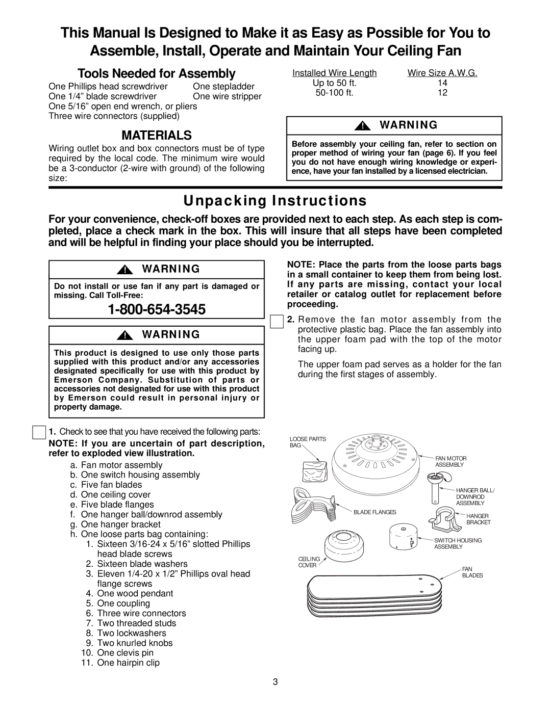
Installation of the CF715 series is straightforward, thanks to the user-friendly guide and included mounting hardware. The fans are designed for standard ceiling installation, making them accessible for most DIY enthusiasts.
In summary, the Emerson CF715 series ceiling fans combine stylish design with advanced technology and efficient performance. With features like quiet operation, versatile airflow, and easy installation, these fans are a smart investment for enhancing indoor comfort and aesthetics in any home. Whether choosing the CF715WB00, CF715S00, CF715AW00, CF715AB00, or CF715PW00, customers can expect a quality product that meets their ceiling fan needs.