CF720PW00, CF720WB00, CF720ORB00 specifications
The Emerson CF720 series ceiling fans, which includes the models CF720PW00, CF720ORB00, and CF720WB00, are designed to enhance both the aesthetic and functional aspects of home environments. These fans come with several advanced features and technologies, making them an ideal choice for any room in the house.One of the standout features of the Emerson CF720 models is their sleek design, which is available in three distinct finishes: Pure White (PW), Oil-Rubbed Bronze (ORB), and Walnut (WB). This variety allows homeowners to choose a fan that complements their interior decor, whether it's a contemporary, traditional, or rustic setting. The clean lines and elegant profiles of these fans ensure they look good while providing excellent airflow.
In terms of performance, the CF720 fans are equipped with powerful and efficient motors that are engineered for durability and quiet operation. This makes them perfect for use in bedrooms, living rooms, or any area where peace and tranquility are desired. The fans boast an impressive airflow capability, making them suitable for larger spaces while maintaining energy efficiency.
The Emerson CF720 series incorporates a reversible motor, allowing for versatility in airflow direction. In warm months, the fan can create a refreshing breeze by spinning counterclockwise. Conversely, in cooler months, the fan can be reversed to distribute heat evenly throughout the room, ensuring comfort year-round.
Another remarkable feature is the fan's compatibility with various control options. The CF720 fans can be used with pull chain controls for easy manual operation, while also being compatible with remote control systems for added convenience. This adaptability is a significant advantage for those who appreciate modern home automation.
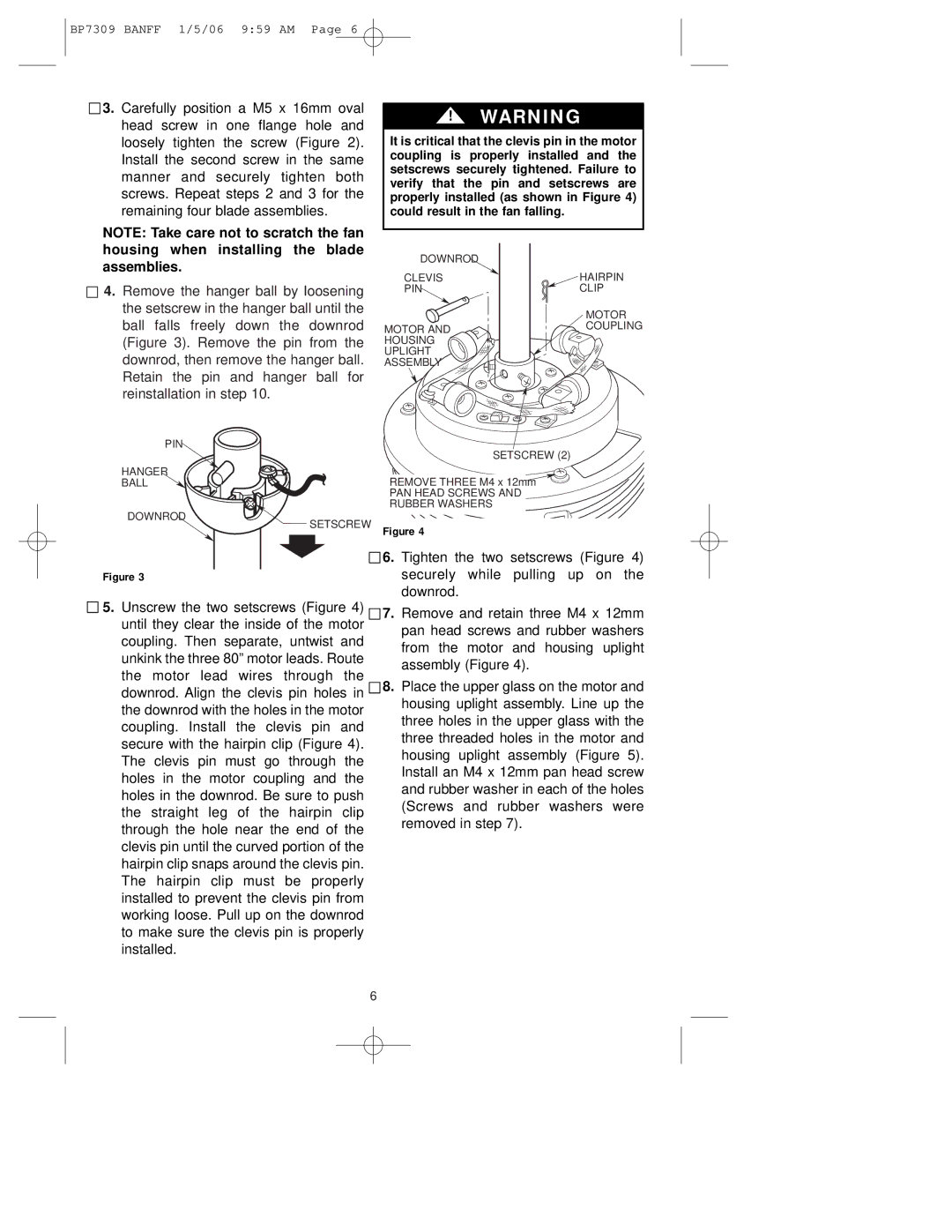
Furthermore, the Emerson CF720 models are engineered for easy installation, with a template that simplifies the mounting process. Each fan also incorporates high-quality materials, ensuring long-lasting performance and reliability. Safety features, such as secure blade attachments, further enhance their usability.
The Emerson CF720PW00, CF720ORB00, and CF720WB00 ceiling fans represent a harmonious blend of style, functionality, and innovation. With their energy-efficient motors, versatile control options, and aesthetic appeal, they are an excellent investment for enhancing the comfort and ambiance of any living space.