Chapter 1 Product Features
Note SCSI signals leading to connector P15 go through zero ohm resistors
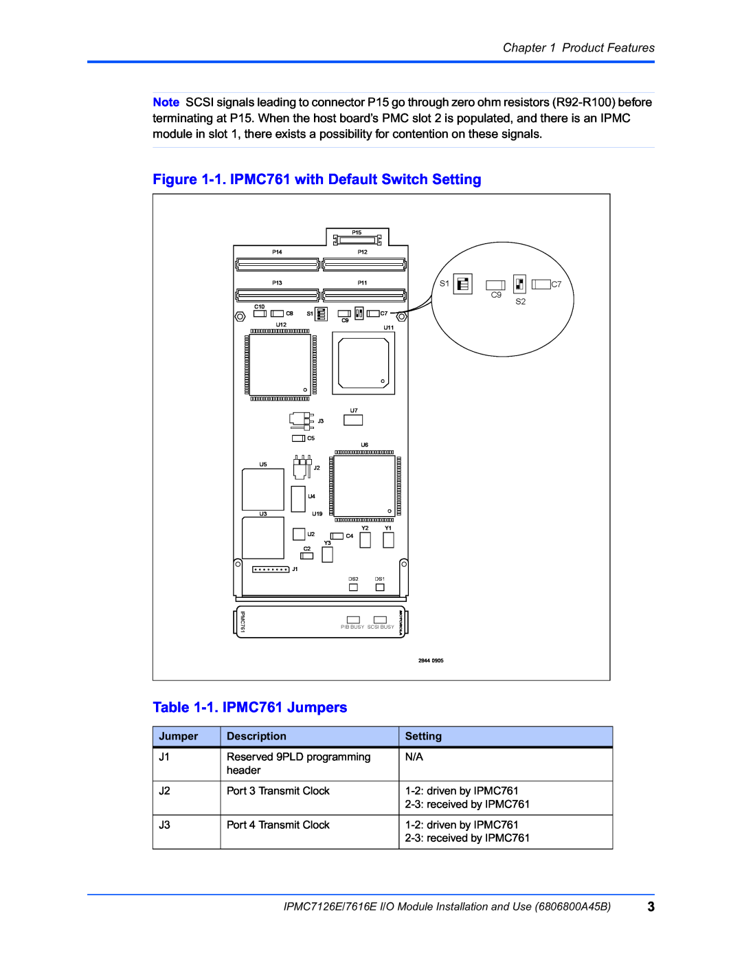
Figure 1-1. IPMC761 with Default Switch Setting
|
| P15 |
|
|
|
P14 |
| P12 |
|
|
|
P13 |
| P11 | S1 | C9 | C7 |
|
|
|
| S2 | |
C10 |
|
|
|
| |
|
|
|
|
| |
C8 | S1 | C9 | C7 |
|
|
U12 |
|
|
|
| |
|
| U11 |
|
| |
|
|
|
|
| |
|
| U7 |
|
|
|
| J3 |
|
|
|
|
| C5 | U6 |
|
|
|
|
|
|
|
| |
U5 | J2 |
|
|
|
|
|
|
|
|
| |
| U4 |
|
|
|
|
U3 | U19 |
|
|
|
|
| U2 | Y2 | Y1 |
|
|
| C4 |
|
|
| |
| C2 | Y3 |
|
|
|
|
|
|
|
| |
J1 |
|
|
|
|
|
|
| DS2 | DS1 |
|
|
IPMC761 |
| PIB BUSY SCSI BUSY |
|
| |
|
|
|
|
| |
|
|
| 2844 0905 |
|
|
Table 1-1. IPMC761 Jumpers
Jumper | Description | Setting |
J1 | Reserved 9PLD programming | N/A |
| header |
|
|
|
|
J2 | Port 3 Transmit Clock | |
|
| |
|
|
|
J3 | Port 4 Transmit Clock | |
|
| |
|
|
|
IPMC7126E/7616E I/O Module Installation and Use (6806800A45B) | 3 |
