Chapter 4 Connector Pin Assignments
PCI Interface and I/O Connectors
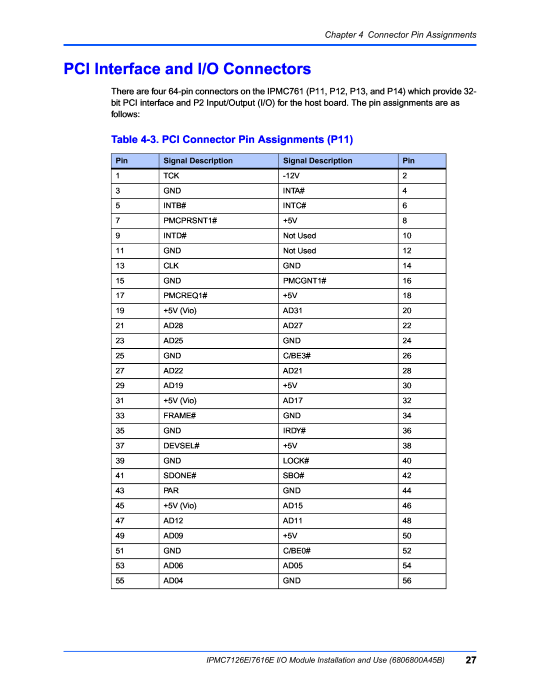
There are four
Table 4-3. PCI Connector Pin Assignments (P11)
Pin | Signal Description | Signal Description | Pin |
1 | TCK | 2 | |
|
|
|
|
3 | GND | INTA# | 4 |
|
|
|
|
5 | INTB# | INTC# | 6 |
|
|
|
|
7 | PMCPRSNT1# | +5V | 8 |
|
|
|
|
9 | INTD# | Not Used | 10 |
|
|
|
|
11 | GND | Not Used | 12 |
|
|
|
|
13 | CLK | GND | 14 |
|
|
|
|
15 | GND | PMCGNT1# | 16 |
|
|
|
|
17 | PMCREQ1# | +5V | 18 |
|
|
|
|
19 | +5V (Vio) | AD31 | 20 |
|
|
|
|
21 | AD28 | AD27 | 22 |
|
|
|
|
23 | AD25 | GND | 24 |
|
|
|
|
25 | GND | C/BE3# | 26 |
|
|
|
|
27 | AD22 | AD21 | 28 |
|
|
|
|
29 | AD19 | +5V | 30 |
|
|
|
|
31 | +5V (Vio) | AD17 | 32 |
|
|
|
|
33 | FRAME# | GND | 34 |
|
|
|
|
35 | GND | IRDY# | 36 |
|
|
|
|
37 | DEVSEL# | +5V | 38 |
|
|
|
|
39 | GND | LOCK# | 40 |
|
|
|
|
41 | SDONE# | SBO# | 42 |
|
|
|
|
43 | PAR | GND | 44 |
|
|
|
|
45 | +5V (Vio) | AD15 | 46 |
|
|
|
|
47 | AD12 | AD11 | 48 |
|
|
|
|
49 | AD09 | +5V | 50 |
|
|
|
|
51 | GND | C/BE0# | 52 |
|
|
|
|
53 | AD06 | AD05 | 54 |
|
|
|
|
55 | AD04 | GND | 56 |
|
|
|
|
IPMC7126E/7616E I/O Module Installation and Use (6806800A45B) | 27 |