1.Sensor Installation
1.1 General description
Each Mobrey ultrasonic sensor contains two piezoelectric crystals. A high frequency signal (1 MHz or 3.7 MHz) generated by the control unit is transmitted to one piezoelectric crystal by coaxial cable. This crystal converts the electrical signal into an ultrasonic oscillation.
The sensor design allows the ultrasonic oscillation to pass from the transmitter crystal to the receiver piezoelectric crystal. Most Mobrey sensors (300 or 400 series) are “gap” type sensors, where the two piezoelectric crystals are separated by a gap. When the gap is in liquid the signal reaches the receiver, because of the low ultrasonic attenuation of the liquid. When the gap is filled with air, no ultrasonic signal can pass from transmitter to receiver.
See figure 1.
Fig 1.
When the gap is filled with liquid, the piezoelectric receiver crystal converts the ultrasonic wave into an electrical signal, which is transmitted back to the control unit using a second coaxial cable. Usually the two coaxial cables to the sensor are in one overall sheath. The control unit circuitry is a feedback amplifier, which oscillates when the sensor is wet, and is quiescent for the sensor dry. The “oscillating” or “non- oscillating” sensor states dictate the output relay states of the MCU200.
For sludge blanket or interface detection the sensor “oscillates” in a clear liquid, and is
For Mobrey Hisens sensors, (type numbers HL, HD etc) the metal body of the sensor provides the ultrasonic coupling between the piezoelectric crystals. This coupling is reduced when the sensor is under a liquid, so that for Hisens sensors “oscillating” state is dry, in air, and the “non oscillating” state is wet, submerged in a liquid.
1.2 Switching levels and orientation
Mobrey gap sensors should normally be mounted with the gap vertical, to avoid build up of solids on the sensor faces on either side of the gap. In this condition the switching level will be half way up the face: if the sensor is mounted from the side of the tank this is normally on the centreline of the cylindrical body.
Occasionally such sensors are mounted with the sensor faces horizontal, either to avoid air bubbles passing through the gap or for convenience of installation.
In this case the switching level will be at the sensor face at the top of the gap.
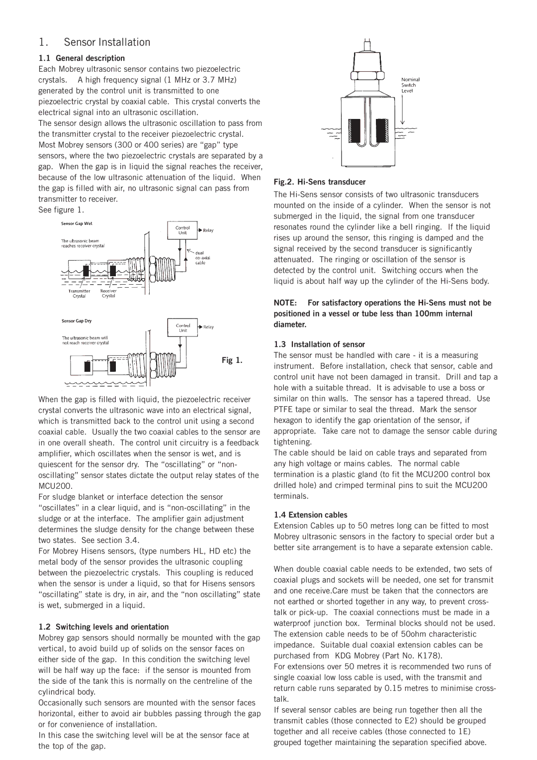
Fig.2. Hi-Sens transducer
The
NOTE: For satisfactory operations the
1.3 Installation of sensor
The sensor must be handled with care - it is a measuring instrument. Before installation, check that sensor, cable and control unit have not been damaged in transit. Drill and tap a hole with a suitable thread. It is advisable to use a boss or similar on thin walls. The sensor has a tapered thread. Use PTFE tape or similar to seal the thread. Mark the sensor hexagon to identify the gap orientation of the sensor, if appropriate. Take care not to damage the sensor cable during tightening.
The cable should be laid on cable trays and separated from any high voltage or mains cables. The normal cable termination is a plastic gland (to fit the MCU200 control box drilled hole) and crimped terminal pins to suit the MCU200 terminals.
1.4 Extension cables
Extension Cables up to 50 metres long can be fitted to most Mobrey ultrasonic sensors in the factory to special order but a better site arrangement is to have a separate extension cable.
When double coaxial cable needs to be extended, two sets of coaxial plugs and sockets will be needed, one set for transmit and one receive.Care must be taken that the connectors are not earthed or shorted together in any way, to prevent cross- talk or
For extensions over 50 metres it is recommended two runs of single coaxial low loss cable is used, with the transmit and return cable runs separated by 0.15 metres to minimise cross- talk.
If several sensor cables are being run together then all the transmit cables (those connected to E2) should be grouped together and all receive cables (those connected to 1E) grouped together maintaining the separation specified above.