MODEL 410VP | WIRING |
WIRING
| orange | current |
| white | voltage |
RTD | black | voltage |
| gray | current |
|
|
red
RTD in
white/red
RTD sense
white
RTD return
RTD RTN RTD SENSE RTD IN RTD SHLD
4CT B 4CT A
SHLD 2CT
SEN 2CT B
SHLD 2CT
SEN 2CT A
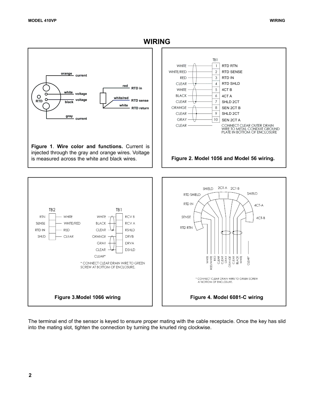
Figure 1. Wire color and functions. Current is injected through the gray and orange wires. Voltage is measured across the white and black wires.
Figure 2. Model 1056 and Model 56 wiring.
Figure 3.Model 1066 wiring
Figure 4. Model 6081-C wiring
The terminal end of the sensor is keyed to ensure proper mating with the cable receptacle. Once the key has slid into the mating slot, tighten the connection by turning the knurled ring clockwise.
2