Installation | |
|
|
2.5Process and Instrumentation Diagrams (P&IDs)
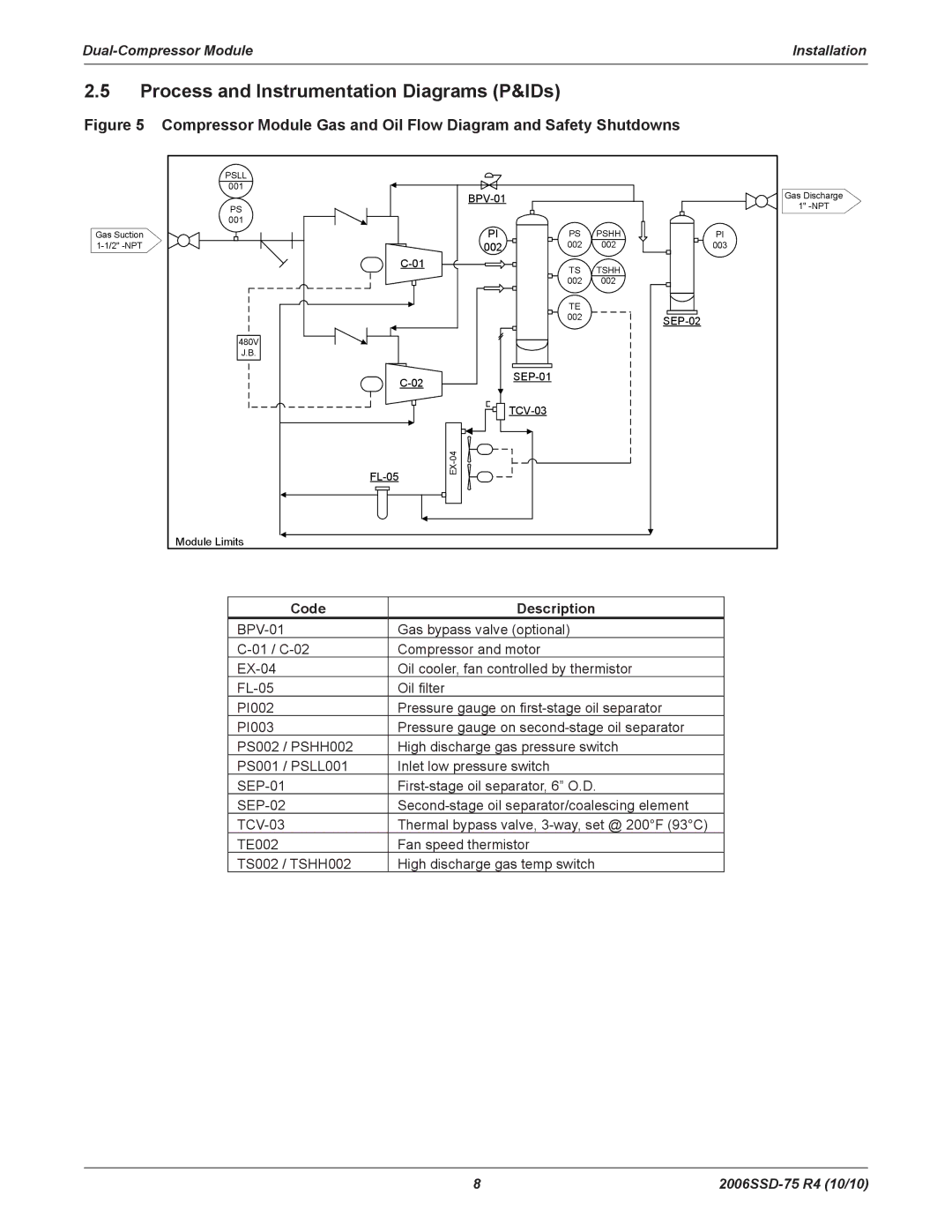
Figure 5 Compressor Module Gas and Oil Flow Diagram and Safety Shutdowns
| PSLL |
|
|
|
|
| 001 |
|
| Gas Discharge | |
|
|
|
| ||
| PS |
|
|
| 1" |
| 001 |
|
|
|
|
Gas Suction |
| PI | PS | PSHH | PI |
| 002 | 002 | 002 | 003 | |
|
| TS | TSHH |
| |
|
|
|
| ||
|
|
| 002 | 002 |
|
|
|
| TE |
|
|
|
|
| 002 |
| |
| 480V |
|
|
|
|
| J.B. |
|
|
|
|
|
|
|
| ||
|
|
|
|
| |
|
|
|
|
| |
|
|
|
| ||
|
|
|
|
| |
| Module Limits |
|
|
|
|
Code | Description |
Gas bypass valve (optional) | |
Compressor and motor | |
Oil cooler, fan controlled by thermistor | |
Oil filter | |
PI002 | Pressure gauge on |
PI003 | Pressure gauge on |
PS002 / PSHH002 | High discharge gas pressure switch |
PS001 / PSLL001 | Inlet low pressure switch |
Thermal bypass valve, | |
TE002 | Fan speed thermistor |
TS002 / TSHH002 | High discharge gas temp switch |
8 |
