Installation | |
|
|
2.6.5Wiring
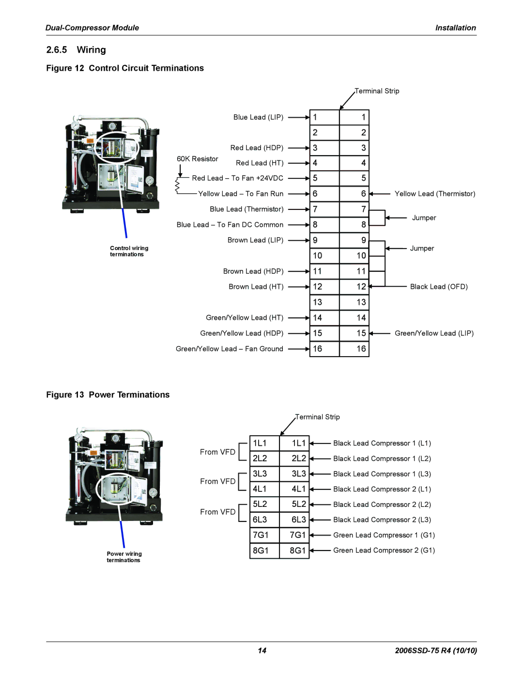
Figure 12 Control Circuit Terminations
|
|
|
|
| Blue Lead (LIP) |
|
| 1 |
|
|
|
|
|
| |||
|
|
|
|
|
|
| 2 | |
| 60K Resistor | Red Lead (HDP) |
|
| 3 | |||
|
| |||||||
| Red Lead (HT) |
|
| 4 | ||||
|
|
|
|
|
|
| ||
|
|
|
|
|
| |||
|
|
| Red Lead – To Fan +24VDC |
|
| 5 | ||
|
|
|
| |||||
|
|
|
| |||||
|
|
|
| Yellow Lead – To Fan Run |
|
| 6 | |
|
|
|
|
| ||||
|
|
|
| Blue Lead (Thermistor) |
|
| 7 | |
| ||||||||
Blue Lead – To Fan DC Common |
|
| 8 | |||||
| ||||||||
Control wiring | Brown Lead (LIP) |
|
| 9 | ||||
| ||||||||
|
|
| 10 | |||||
terminations |
|
| ||||||
|
|
|
|
| Brown Lead (HDP) |
|
| 11 |
|
|
|
|
|
| |||
|
|
|
|
| Brown Lead (HT) |
|
| 12 |
|
|
|
|
|
| |||
|
|
|
|
|
|
| 13 | |
|
|
|
| Green/Yellow Lead (HT) |
|
| 14 | |
| ||||||||
|
|
|
| Green/Yellow Lead (HDP) |
|
| 15 | |
| ||||||||
Green/Yellow Lead – Fan Ground |
|
| 16 | |||||
| ||||||||
|
|
|
|
|
|
|
|
|
Terminal Strip
1 |
| |
2 |
| |
3 |
| |
4 |
| |
5 |
| |
6 | Yellow Lead (Thermistor) | |
7 | Jumper | |
8 | ||
| ||
9 | Jumper | |
10 | ||
| ||
11 |
| |
12 | Black Lead (OFD) | |
13 |
| |
14 |
| |
15 | Green/Yellow Lead (LIP) | |
16 |
|
Figure 13 Power Terminations
From VFD
From VFD
From VFD
Power wiring terminations
| Terminal Strip | ||||
|
|
|
|
|
|
1L1 | 1L1 |
|
| Black Lead Compressor 1 (L1) | |
| |||||
|
|
|
|
|
|
2L2 | 2L2 |
|
| Black Lead Compressor 1 (L2) | |
| |||||
|
|
|
|
|
|
3L3 | 3L3 |
|
| Black Lead Compressor 1 (L3) | |
| |||||
|
|
|
|
|
|
4L1 | 4L1 |
|
| Black Lead Compressor 2 (L1) | |
| |||||
|
|
|
|
|
|
5L2 | 5L2 |
|
| Black Lead Compressor 2 (L2) | |
| |||||
|
|
|
|
|
|
6L3 | 6L3 |
|
| Black Lead Compressor 2 (L3) | |
| |||||
|
|
|
|
|
|
7G1 | 7G1 |
|
| Green Lead Compressor 1 (G1) | |
| |||||
|
|
|
|
| |
8G1 | 8G1 |
|
| Green Lead Compressor 2 (G1) | |
| |||||
|
|
|
|
|
|
14 |