Manuals
/
Emerson
/
Household Appliance
/
Carbon Monoxide Alarm
Emerson
UT-P+-STXXXX, MA N-00 05-00
user manual
Models:
MA N-00 05-00
UT-P+-STXXXX
1
18
44
44
Download
44 pages
2.25 Kb
15
16
17
18
19
20
21
22
Troubleshooting
Specification
Install
Wiring Diagrams
Default Relay Settings
Start Delay
Wiring
Dimension
Calibration Procedure
Review Settings
Page 18
Image 18
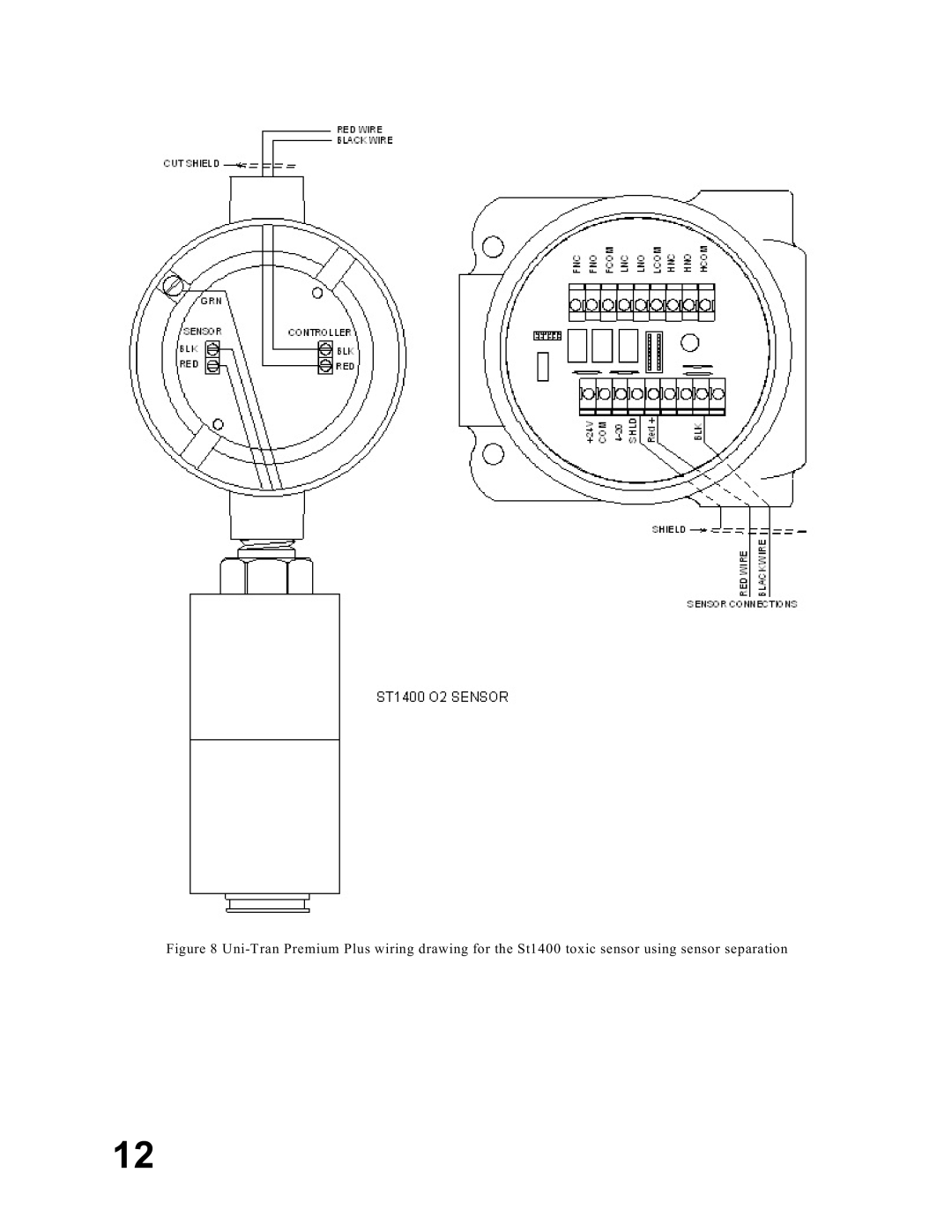
Figure 8
Uni-Tran
Premium Plus wiring drawing for the St1400 toxic sensor using sensor separation
12
Page 17
Page 19
Page 18
Image 18
Page 17
Page 19
Contents
UNI-TRAN Premium Plus Toxic GAS Detector UT-P+-STXXXX
Page
Page
Page
Table of Contents
Page
Features
Introduction
Introduction
Location of Sensors
Installation and Start Up
What’s in the package
Unpacking
Mounting
Toxic Detector Layout
Dimensional Drawings
Page
Page
Page
Wiring
Sensor Separation
Page
Wiring Diagrams
Page
Page
Page
Page
Page
Installation Checklist
Start Up
Relay Settings
Default Relay Settings
Summary of Main Menu
Exit Return to normal if no option is selected
Review Settings
System Calibration
Calibration Procedure
Page
Operation
Periodic Response Check
Operator Interface
Calibration Procedure
Table of Responses
Magnetic Reed Switch Activation
Relay Settings
Review Settings
Hardware
Start Delay
Sensor Fault
Sensor Drift
Relays
20 mA
Troubleshooting
Sensor Life
Glossary of Terms
Ordering Information
Published in a ccordance w ith E1A standard
Appendix B Wire Resistance In Ohms
AWG
Appendix C Specifications
Sensor Specifications
Page
Top
Page
Image
Contents