EC2-352 Display Case and Coldroom Controller

Operating Instructions

GB

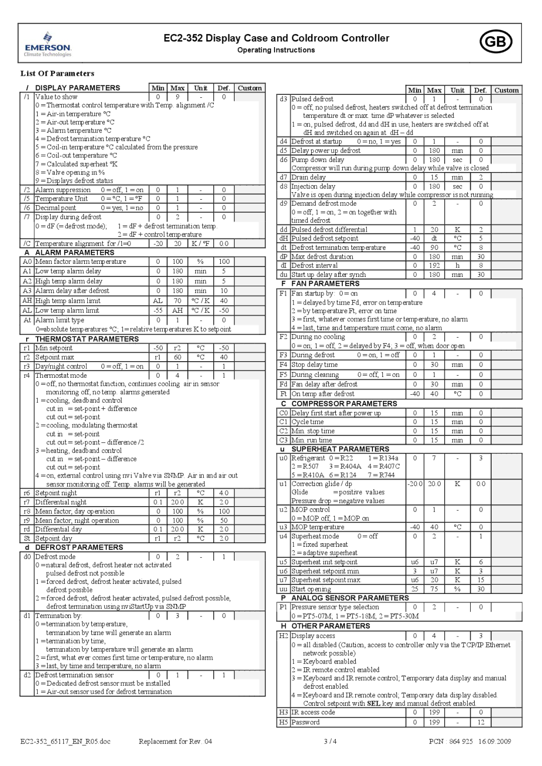
List Of Parameters

/

DISPLAY PARAMETERS


Min


Max

Unit


Def.

Custom

/1

Value to show


0


9

-


0


0

= Thermostat control temperature with Temp. alignment /C


1

= Air-in temperature °C


2

= Air-out temperature °C


3

= Alarm temperature °C


4

= Defrost termination temperature °C


5

= Coil-in temperature °C calculated from the pressure


6

= Coil-out temperature °C


7

= Calculated superheat °K


8

= Valve opening in %


9

= Displays defrost status


/2

Alarm suppression

0 = off, 1 = on


0


1

-


0


/5

Temperature Unit

0 = °C, 1 = °F


0


1

-


0


/6

Decimal point

0 = yes, 1 = no


0


1

-


0


/7

Display during defrost


0


2

-


0


0

= dF (= defrost mode); 1 = dF +

defrost termination temp.


2 = dF + control temperature


/C

Temperature alignment for /1=0


-20


20

K / °F


0.0


A

ALARM PARAMETERS


A0

Mean factor alarm temperature


0


100

%


100


A1

Low temp alarm delay


0


180

min


5


A2

High temp alarm delay


0


180

min


5


A3

Alarm delay after defrost


0


180

min


10


AH

High temp alarm limit


AL


70

°C / K


40


AL

Low temp alarm limit


-55


AH

°C / K


-50


At

Alarm limit type


0


1

-


0


0=absolute temperatures °C; 1= relative

temperatures K to setpoint


r

THERMOSTAT PARAMETERS


r1

Min setpoint


-50


r2

°C


-50


r2

Setpoint max


r1


60

°C


40


r3

Day/night control

0 = off, 1 = on


0


1

-


1


r4

Thermostat mode


0


4

-


1


0

= off, no thermostat function, continues

cooling air in sensor


monitoring off, no temp. alarms generated


1

= cooling, deadband control


cut in = set-point + difference


cut out = set-point


2

= cooling, modulating thermostat


cut in = set-point


cut out = set-point – difference /2


3

= heating, deadband control


cut in = set-point – difference


cut out = set-point


4

= on, external control using nvi Valve via SNMP. Air in and air out


sensor monitoring off. Temp. alarms will be generated


r6

Setpoint night


r1


r2

°C


4.0


r7

Differential night


0.1


20.0

K


2.0


r8

Mean factor, day operation


0


100

%


100


r9

Mean factor, night operation


0


100

%


50


rd

Differential day


0.1


20.0

K


2.0


St

Setpoint day


r1


r2

°C


2.0


d

DEFROST PARAMETERS


d0

Defrost mode


0


2

-


1


0

= natural defrost, defrost heater not

activated


pulsed defrost not possible


1

= forced defrost, defrost heater activated, pulsed


defrost possible


2

= forced defrost, defrost heater activated, pulsed defrost possible,


defrost termination using nviStartUp via SNMP


d1

Termination by:


0


3

-


0


0

= termination by temperature,


termination by time will generate an alarm


1

= termination by time,


termination by temperature will generate an alarm


2

= first, what ever comes first time or temperature, no alarm


3

= last, by time and temperature, no alarm


d2

Defrost termination sensor


0


1

-


1


0

= Dedicated defrost sensor must be

installed


1

= Air-out sensor used for defrost termination


EC2-352_65117_EN_R05.doc

Replacement for Rev.:04


Min

Max

Unit


Def.

Custom

d3

Pulsed defrost


0

1

-


0


0

= off, no pulsed defrost, heaters switched off at defrost termination


temperature dt or max. time dP whatever is selected


1

= on, pulsed defrost, dd and dH in use, heaters are switched off at


dH and switched on again at dH – dd


d4

Defrost at startup

0 = no, 1 = yes

0

1

-


0


d5

Delay power up defrost


0

180

min


0


d6

Pump down delay


0

180

sec


0


Compressor will run during pump down

delay

while

valve is

closed


d7

Drain delay


0

15

min


2


d8

Injection delay


0

180

sec


0


Valve is open during injection delay while compressor is not running


d9

Demand defrost mode


0

2

-


0


0

= off, 1 = on, 2 = on together with


timed defrost


dd

Pulsed defrost differential

1

20

K


2


dH

Pulsed defrost setpoint


-40

dt

°C


5


dt

Defrost termination temperature

-40

90

°C


8


dP

Max defrost duration


0

180

min


30


dI

Defrost interval


0

192

h


8


du

Start up delay after synch

0

180

min


30


F

FAN PARAMETERS


F1

Fan startup by: 0 = on


0

4

-


0


1

= delayed by time Fd, error on temperature


2

= by temperature Ft, error on time


3

= first, whatever comes first time or temperature, no alarm


4

= last, time and temperature must come, no alarm


F2

During no cooling


0

2

-


0


0

= on; 1 = off; 2 = delayed by F4; 3 =

off, when door open


F3

During defrost

0 = on, 1 = off

0

1

-


0


F4

Stop delay time


0

30

min


0


F5

During cleaning

0 = off, 1 = on

0

1

-


0


Fd

Fan delay after defrost


0

30

min


0


Ft

On temp after defrost


-40

40

°C


0


C

COMPRESSOR PARAMETERS


C0

Delay first start after power up

0

15

min


0


C1

Cycle time


0

15

min


0


C2

Min. stop time


0

15

min


0


C3

Min. run time


0

15

min


0


u

SUPERHEAT PARAMETERS


u0

Refrigerant

0 = R22


1 = R134a

0

7

-


3


2

= R507 3 = R404A

4 = R407C


5

= R410A

6 = R124


7 = R744


u1

Correction glide / dp


-20.0

20.0

K


0.0


Glide

= positive

values


Pressure drop = negative values


u2

MOP control


0

1

-


0


0

= MOP off, 1 = MOP on


u3

MOP temperature


-40

40

°C


0


u4

Superheat mode

0 = off

0

2

-


1


1

= fixed superheat


2

= adaptive superheat


u5

Superheat init setpoint


u6

u7

K


6


u6

Superheat setpoint min.


3

u7

K


3


u7

Superheat setpoint max.


u6

20

K


15


uu

Start opening


25

75

%


30


P

ANALOG SENSOR PARAMETERS


P1

Pressure sensor type selection

0

2

-


0


0

= PT5-07M; 1 = PT5-18M; 2 = PT5-

30M


H

OTHER PARAMETERS


H2

Display access


0

4

-


3


0

= all disabled (Caution, access to controller only via the TCP/IP

Ethernet


network possible)


1

= Keyboard enabled


2

= IR remote control enabled


3

= Keyboard and IR remote control; Temporary data display and manual


defrost enabled.


4

= Keyboard and IR remote control; Temporary data display disabled.


Control setpoint with SEL key and manual defrost enabled.


H3

IR access code


0

199

-


0


H5

Password


0

199

-


12


3 / 4


PCN : 864 925

16.09.2009


Page 3
Image 3
Emerson Process Management EC2-352 user manual List Of Parameters, Min Max Unit Def

EC2-352 specifications

Emerson Process Management has consistently been at the forefront of industrial automation and process control technologies, and the EC2-352 is a testament to their commitment to innovation and excellence. This device is part of Emerson's broader portfolio aimed at improving operational efficiency, reliability, and safety in various process environments.

The EC2-352 is designed as a robust and flexible platform for monitoring and control applications. One of its main features is its adaptability to a wide variety of environments, making it suitable for diverse industries including oil and gas, chemicals, pharmaceuticals, and food processing. This versatility is underpinned by its ability to connect seamlessly with existing systems and equipment.

One of the defining technologies integrated into the EC2-352 is its advanced communication capabilities. It supports multiple communication protocols such as HART, MODBUS, and Ethernet/IP, facilitating easy integration with both legacy and modern systems. This ensures that users can maintain a high level of interoperability in their operations.

The device is equipped with a powerful processing engine, which allows for real-time data acquisition and analysis. This feature is essential for making informed decisions based on the latest information, ultimately leading to improved operational performance. Additionally, the EC2-352 offers built-in diagnostics and predictive maintenance capabilities. These tools not only enhance reliability but also extend the lifecycle of equipment by proactively addressing potential issues before they become critical.

Another significant characteristic of the EC2-352 is its user-friendly interface. With intuitive controls and a clear display, operators can easily configure settings and monitor system performance. This user-centric design minimizes training time and mitigates the risk of operator error.

Moreover, the EC2-352 is built with rugged durability in mind. Its construction is optimized for harsh environmental conditions, ensuring consistent performance even in extreme temperatures or challenging operational scenarios. This resilience translates to lower maintenance costs and decreased downtime.

In conclusion, the Emerson Process Management EC2-352 exemplifies the evolution of process control technology. Through its advanced features, robust processing capabilities, and comprehensive communication options, it stands out as a vital tool for industries seeking to enhance their operational efficiency and reliability. With the EC2-352, Emerson continues to lead the way in delivering solutions that meet the demands of modern industrial environments.