Orienting the Sensor
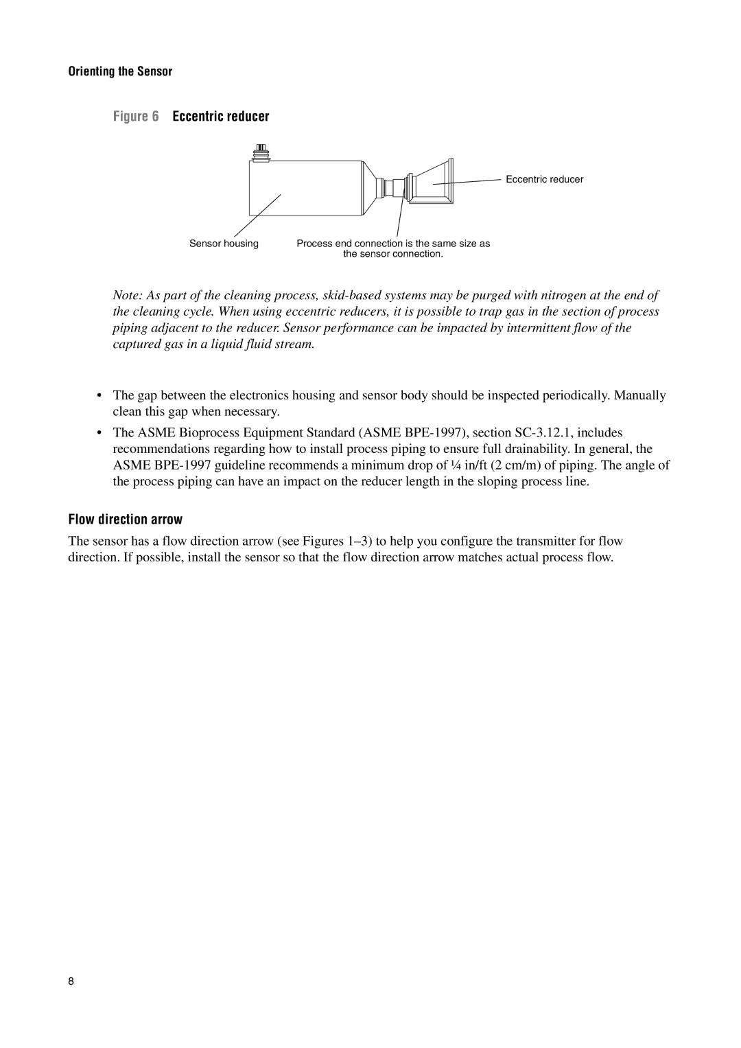
Figure 6 Eccentric reducer
Eccentric reducer
Sensor housing | Process end connection is the same size as |
| the sensor connection. |
Note: As part of the cleaning process, skid-based systems may be purged with nitrogen at the end of the cleaning cycle. When using eccentric reducers, it is possible to trap gas in the section of process piping adjacent to the reducer. Sensor performance can be impacted by intermittent flow of the captured gas in a liquid fluid stream.
•The gap between the electronics housing and sensor body should be inspected periodically. Manually clean this gap when necessary.
•The ASME Bioprocess Equipment Standard (ASME BPE-1997), section SC-3.12.1, includes recommendations regarding how to install process piping to ensure full drainability. In general, the ASME BPE-1997 guideline recommends a minimum drop of ¼ in/ft (2 cm/m) of piping. The angle of the process piping can have an impact on the reducer length in the sloping process line.
Flow direction arrow
The sensor has a flow direction arrow (see Figures 1–3) to help you configure the transmitter for flow direction. If possible, install the sensor so that the flow direction arrow matches actual process flow.

