Check belt tension. Drive packages are supplied with fiber- glass belts that must be properly tensioned at installation because they do not stretch. The belt should deflect 3/16" per foot of belt span with a 2 or
ELECTRICAL CONNECTIONS
The electric box ships complete with motor starter, transform- ers, relays and terminal block for making field connections. Remember: One air handlers with factory installed pump out solenoids, wires to the solenoid must be field connected.
Refer to Figures 30 & 31 for Indoor Unit Wiring Diagrams.
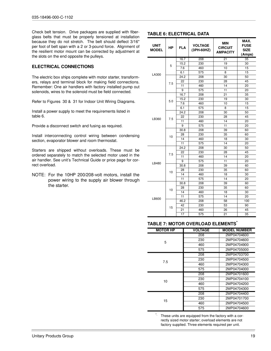
Install a power supply to meet the requirements listed in table 6.
Provide a disconnect switch and fusing as required.
Install interconnecting control wiring between condensing section, evaporator blower and room thermostat.
Starters are shipped without overloads. These must be ordered separately to match the selected motor used in the air handler. See unit’s Technical Guide or price page for cor- rect overload.
NOTE: For the 10HP
TABLE 6: ELECTRICAL DATA
|
|
|
| MIN | MAX. | |
UNIT |
|
| VOLTAGE | FUSE | ||
HP | FLA | CIRCUIT | ||||
MODEL | SIZE | |||||
|
| AMPACITY | ||||
|
|
|
| (Amps) | ||
|
|
|
|
| ||
|
|
|
|
|
| |
|
| 16.7 | 208 | 21 | 35 | |
| 5 | 15.2 | 230 | 19 | 30 | |
|
|
|
|
| ||
| 7.6 | 460 | 10 | 15 | ||
|
| |||||
|
|
|
|
|
| |
LA300 |
| 6.1 | 575 | 8 | 15 | |
|
|
|
|
| ||
| 24.2 | 208 | 30 | 50 | ||
|
| |||||
|
|
|
|
|
| |
| 7.5 | 22 | 230 | 28 | 45 | |
|
|
|
|
| ||
| 11 | 460 | 14 | 20 | ||
|
| |||||
|
|
|
|
|
| |
|
| 9 | 575 | 11 | 20 | |
|
|
|
|
|
| |
|
| 16.7 | 208 | 21 | 35 | |
|
|
|
|
|
| |
| 5.0 | 15.2 | 230 | 19 | 30 | |
|
|
|
|
| ||
| 7.6 | 460 | 10 | 15 | ||
|
| |||||
|
|
|
|
|
| |
|
| 6.1 | 575 | 8 | 15 | |
|
|
|
|
|
| |
|
| 24.2 | 208 | 30 | 50 | |
|
|
|
|
|
| |
LB360 | 7.5 | 22 | 230 | 28 | 45 | |
|
|
|
| |||
11 | 460 | 14 | 20 | |||
|
| |||||
|
|
|
|
|
| |
|
| 9 | 575 | 11 | 20 | |
|
|
|
|
|
| |
|
| 30.8 | 208 | 39 | 60 | |
|
|
|
|
|
| |
| 10 | 28 | 230 | 35 | 60 | |
|
|
|
|
| ||
| 14 | 460 | 18 | 30 | ||
|
| |||||
|
|
|
|
|
| |
|
| 11 | 575 | 14 | 20 | |
|
|
|
|
|
| |
|
| 24.2 | 208 | 30 | 50 | |
|
|
|
|
|
| |
| 7.5 | 22 | 230 | 28 | 45 | |
|
|
|
|
| ||
| 11 | 460 | 14 | 20 | ||
|
| |||||
|
|
|
|
|
| |
LB480 |
| 9 | 575 | 11 | 20 | |
|
|
|
|
| ||
| 30.8 | 208 | 39 | 60 | ||
|
| |||||
|
|
|
|
|
| |
| 10 | 28 | 230 | 35 | 60 | |
|
|
|
|
| ||
| 14 | 460 | 18 | 30 | ||
|
| |||||
|
|
|
|
|
| |
|
| 11 | 575 | 14 | 20 | |
|
|
|
|
|
| |
|
| 30.8 | 208 | 39 | 60 | |
|
|
|
|
|
| |
| 10 | 28 | 230 | 35 | 60 | |
|
|
|
|
| ||
| 14 | 460 | 18 | 30 | ||
|
| |||||
|
|
|
|
|
| |
LB600 |
| 11 | 575 | 14 | 20 | |
|
|
|
|
| ||
| 46.2 | 208 | 58 | 100 | ||
|
| |||||
|
|
|
|
|
| |
| 15 | 42 | 230 | 53 | 90 | |
|
|
|
|
| ||
| 21 | 460 | 26 | 45 | ||
|
| |||||
|
|
|
|
|
| |
|
| 17 | 575 | 21 | 35 |
TABLE 7: MOTOR OVERLOAD ELEMENTS*
MOTOR HP | VOLTAGE | MODEL NUMBER | ||
| 208 | 2MP04704600 | ||
5 | 230 | 2MP04704600 |
| |
|
|
| ||
460 | 2MP04704900 | |||
| ||||
|
|
| ||
| 575 | 2MP04705000 |
| |
| 208 | 2MP04703700 | ||
7.5 | 230 | 2MP04704500 |
| |
|
|
| ||
460 | 2MP04704300 | |||
| ||||
|
|
| ||
| 575 | 2MP04704000 |
| |
| 208 | 2MP04701600 | ||
10 | 230 | 2MP04704100 |
| |
|
|
| ||
460 | 2MP04704200 | |||
| ||||
|
|
| ||
| 575 | 2MP04704300 |
| |
| 208 | 2MP04704400 | ||
15 | 230 | 2MP04701700 |
| |
|
|
| ||
460 | 2MP04704500 | |||
| ||||
|
|
| ||
| 575 | 2MP04704600 |
| |
*. These units are equipped from the factory with a cor- rectly sized motor starter; overload elements are not factory supplied. Three elements required per unit.
Unitary Products Group | 19 |