O U T S I D E C H A N N E L
|
|
|
|
|
|
|
|
|
| 9 / 1 6 " H O L E F O R 1 / 2 " H A N G E R |
|
|
|
|
|
|
|
|
|
| |
|
|
|
|
|
|
|
|
|
| ( 2 P E R C H A N N E L ) |
|
|
|
|
|
|
|
|
| ||
S U S P E N S | I O N C H A N N E |
| L |
| 5 / 1 6 - 1 8 " H E X N U T | |||||
| ||||||||||
5 / 1 6 - 1 8 " H E X N U T |
|
| L O C K W A S H E R | |||||||
| ||||||||||
|
|
|
|
|
|
|
|
|
| 9 / 1 6 " F L A T W A S H E R |
|
|
|
|
|
|
|
|
|
| |
|
|
|
|
|
|
|
|
|
| |
|
|
|
|
|
|
|
|
|
| |
|
|
|
|
|
|
| ||||
|
|
|
|
|
|
|
|
|
|
|
S P A C E R ( 3 / 8 " L O N G ) |
|
|
|
|
|
|
| T O P P A N E L | ||
|
|
|
|
|
|
| ||||
|
|
|
|
|
|
|
|
|
| |
S I D E P A N E L
![]() 9 / 1 6 " F L A T W A S H E R
9 / 1 6 " F L A T W A S H E R
![]() M A C H I N E S C R E W ( 5 / 1 6 - 1 8 X 1 -
M A C H I N E S C R E W ( 5 / 1 6 - 1 8 X 1 -
![]() O U T E R F R A M E O F U N I T S E C T I O ( 1 - 3 / 4 " X 1 - 3 / 4 " )
O U T E R F R A M E O F U N I T S E C T I O ( 1 - 3 / 4 " X 1 - 3 / 4 " )
C E N T E R C H A N N E L ( L o c a t io n " 1 " F ig u
|
| 9 / 1 6 " H O L E F O R 1 / 2 " H A N G E R | |
|
| ||
|
| ( 2 P E R C H A N N E L ) | |
S U S P E N S I O N C H A N N E L | 5 / 1 6 - 1 8 " H E X N U T | ||
5 / 1 6 - 1 8 " H E X N U T | |||
| |||
|
| L O C K W A S H E R | |
T O P P A N E L
9 / 1 6 " F L A T W A S H E R
S P A C E R ( 3 / 8 " L O N G )
C E N T E R F R A M E
O F U N I T S E C T I O N S
( 2 1 / 8 " X 3 / 8 " )
T O P P A N E L
9 / 1 6 " | F L A T W A S H E R |
M A C H I N E S C R E W ( 5 / 1 6 - 1 8 X 1 - 1 / 2 | L G ) |
C E N T E R C H A N N E L ( L o c a t io n " 2 " in F i
![]() 9 / 1 6 " H O L E F O R 1 / 2 " H A N G E R R
9 / 1 6 " H O L E F O R 1 / 2 " H A N G E R R
S U S P E N S I O N C H A N N E L
9 / 1 6 " F L A T W A S H E R
T O P P A N E L
( 2 P E R C H A N N E L )
M A C H I N E S C R E W ( 5 / 1 6 - 1 8 X 1 - 1
L O C K W A S H E R
9 / 1 6 " F L A T W A S H E R
S P A C E R ( 1 / 2 " L O N G )
C E N T E R O F U N I T ( 2 1 / 8 "
F R A M E | |
| S E C T I O N S |
X | 3 / 8 " ) |
![]() T O P P A N E L
T O P P A N E L
5 / 1 6 - 1 8 " C A G E N U T
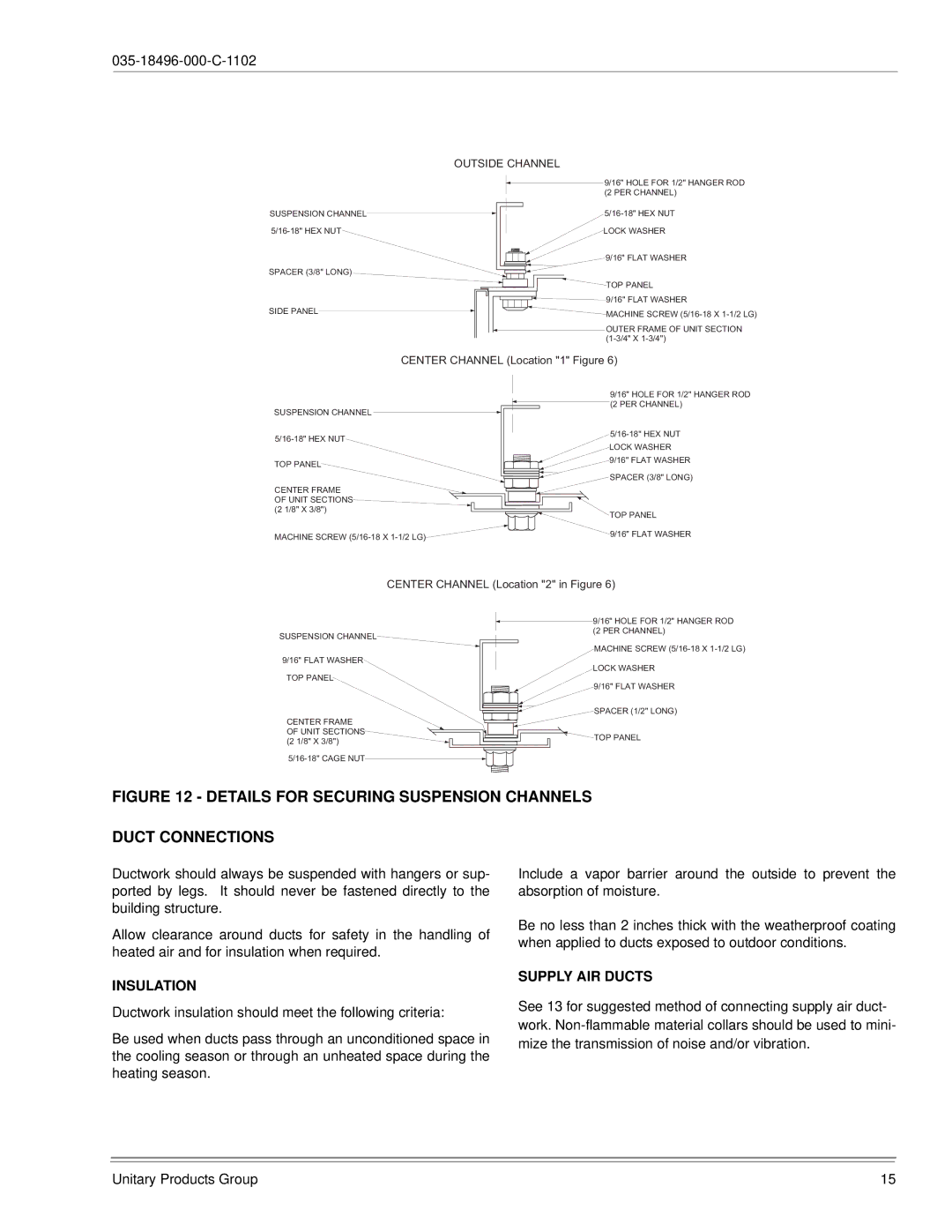
FIGURE 12 - DETAILS FOR SECURING SUSPENSION CHANNELS
DUCT CONNECTIONS
Ductwork should always be suspended with hangers or sup- ported by legs. It should never be fastened directly to the building structure.
Allow clearance around ducts for safety in the handling of heated air and for insulation when required.
INSULATION
Ductwork insulation should meet the following criteria:
Be used when ducts pass through an unconditioned space in the cooling season or through an unheated space during the heating season.
Include a vapor barrier around the outside to prevent the absorption of moisture.
Be no less than 2 inches thick with the weatherproof coating when applied to ducts exposed to outdoor conditions.
SUPPLY AIR DUCTS
See 13 for suggested method of connecting supply air duct- work.
Unitary Products Group | 15 |