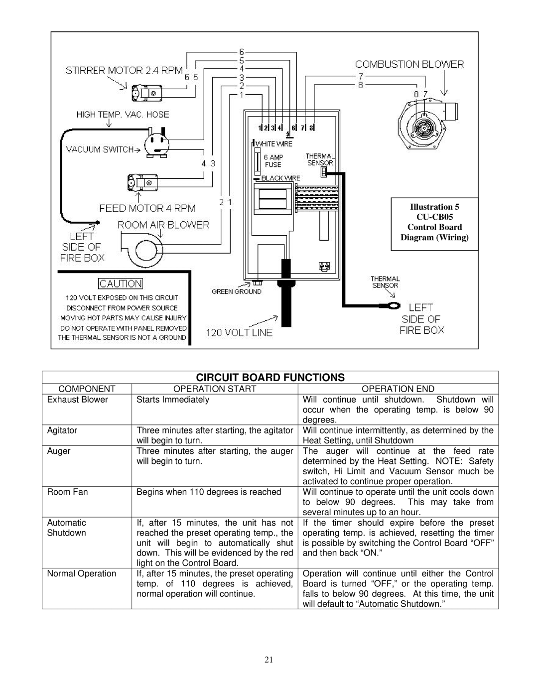
Illustration 5
Control Board
Diagram (Wiring)
CIRCUIT BOARD FUNCTIONS
COMPONENT | OPERATION START | OPERATION END |
|
Exhaust Blower | Starts Immediately | Will continue until shutdown. | Shutdown will |
|
| occur when the operating temp. is below 90 | |
|
| degrees. |
|
Agitator | Three minutes after starting, the agitator | Will continue intermittently, as determined by the | |
| will begin to turn. | Heat Setting, until Shutdown |
|
Auger | Three minutes after starting, the auger | The auger will continue at the feed rate | |
| will begin to turn. | determined by the Heat Setting. | NOTE: Safety |
|
| switch, Hi Limit and Vacuum Sensor much be | |
|
| activated to continue proper operation. | |
Room Fan | Begins when 110 degrees is reached | Will continue to operate until the unit cools down | |
|
| to below 90 degrees. This may take from | |
|
| several minutes up to an hour. |
|
Automatic | If, after 15 minutes, the unit has not | If the timer should expire before the preset | |
Shutdown | reached the preset operating temp., the | operating temp. is achieved, resetting the timer | |
| unit will begin to automatically shut | is possible by switching the Control Board “OFF” | |
| down. This will be evidenced by the red | and then back “ON.” |
|
| light on the Control Board. |
|
|
Normal Operation | If, after 15 minutes, the preset operating | Operation will continue until either the Control | |
| temp. of 110 degrees is achieved, | Board is turned “OFF,” or the operating temp. | |
| normal operation will continue. | falls to below 90 degrees. At this time, the unit | |
|
| will default to “Automatic Shutdown.” | |
21