Connecting to the Network
3.3.2Connecting UTP Cables to the 5H103-48
When facing the front panel of the
To connect a UTP segment to the
1.Ensure that the device connected to the other end of the segment is powered ON.
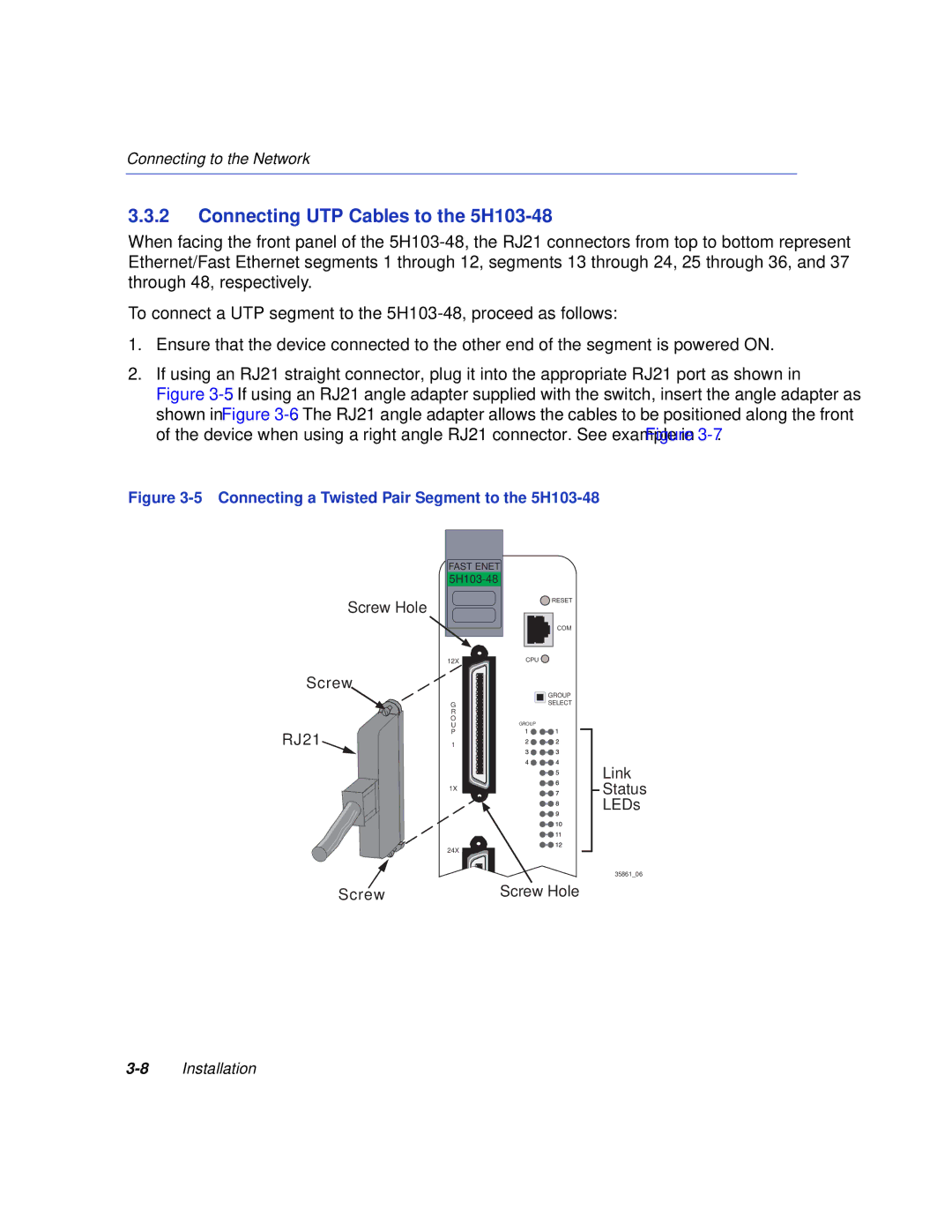
2.If using an RJ21 straight connector, plug it into the appropriate RJ21 port as shown in
Figure 3-5. If using an RJ21 angle adapter supplied with the switch, insert the angle adapter as shown in Figure 3-6. The RJ21 angle adapter allows the cables to be positioned along the front of the device when using a right angle RJ21 connector. See example in Figure 3-7.
Figure 3-5 Connecting a Twisted Pair Segment to the 5H103-48
Screw Hole
Screw
RJ21
Screw
FAST ENET
![]() RESET
RESET
COM
12X | CPU |
| GROUP |
G | SELECT |
R |
|
O | GROUP |
U | |
| GROUP |
P |
|
1 |
|
| Link |
1X | Status |
| LEDs |
24X
35861_06
Screw Hole