Initial Installation
QUALIFIED INSTALLERS ONLY
CATHEDRAL CEILING INSTALLATION:
STEP 1. Follow installation steps 1 & 2 under ‘Vertical Installation’.
STEP 2. Using the plumb bob, mark the centerline of the venting system on the ceiling and drill a small hole through the ceiling and roof at this point. From the roof, locate the drill hole and mark the outline of the “Cathedral Ceiling Support Box”.
STEP 3. Remove shingles or other roof coverings as necessary to cut the rectangular hole for the “Support Box”. Cut the hole 1⁄8” larger than the “Support Box” outline.
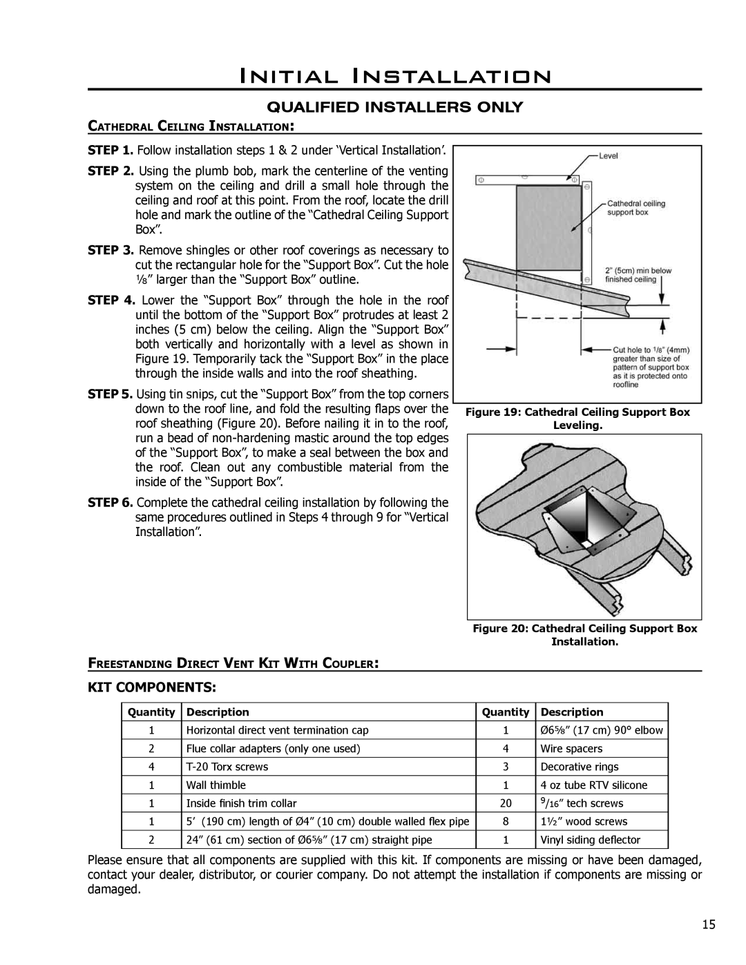
STEP 4. Lower the “Support Box” through the hole in the roof until the bottom of the “Support Box” protrudes at least 2 inches (5 cm) below the ceiling. Align the “Support Box” both vertically and horizontally with a level as shown in Figure 19. Temporarily tack the “Support Box” in the place through the inside walls and into the roof sheathing.
STEP 5. Using tin snips, cut the “Support Box” from the top corners down to the roof line, and fold the resulting flaps over the roof sheathing (Figure 20). Before nailing it in to the roof, run a bead of
STEP 6. Complete the cathedral ceiling installation by following the same procedures outlined in Steps 4 through 9 for “Vertical Installation”.
Figure 19: Cathedral Ceiling Support Box
Leveling.
Figure 20: Cathedral Ceiling Support Box
Installation.
FREESTANDING DIRECT VENT KIT WITH COUPLER:
KIT COMPONENTS:
Quantity | Description | Quantity | Description |
|
|
|
|
1 | Horizontal direct vent termination cap | 1 | Ø65⁄8” (17 cm) 90° elbow |
|
|
|
|
2 | Flue collar adapters (only one used) | 4 | Wire spacers |
|
|
|
|
4 | 3 | Decorative rings | |
|
|
|
|
1 | Wall thimble | 1 | 4 oz tube RTV silicone |
|
|
|
|
1 | Inside finish trim collar | 20 | 9/16” tech screws |
1 | 5’ (190 cm) length of Ø4” (10 cm) double walled flex pipe | 8 | 11⁄2” wood screws |
|
|
|
|
2 | 24” (61 cm) section of Ø65⁄8” (17 cm) straight pipe | 1 | Vinyl siding deflector |
|
|
|
|
Please ensure that all components are supplied with this kit. If components are missing or have been damaged, contact your dealer, distributor, or courier company. Do not attempt the installation if components are missing or damaged.
15