Initial Installation
QUALIFIED INSTALLERS ONLY
PLANNING YOUR INSTALLATION:
When planning your installation, it will be necessary to select the proper length of vent pipe for your particular requirements. It is important to note when passing through a wall, the maximum allowable wall thickness is 10 inches (25.4 cm), 11⁄2 inches (3.8 cm) clearance to combustibles must be maintained. Select the amount of vertical rise desired for
Your total vent pipe length must be within the shaded area of Figure 4. If a 90° elbow is used in the horizontal plane, 36” (91.4 cm) must be subtracted from the allowable horizontal run.
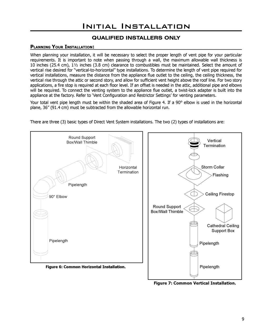
There are three (3) basic types of Direct Vent System installations. The two (2) types of installations are:
Round Support |
Box/Wall Thimble |
Horizontal |
Termination |
Pipelength |
90° Elbow |
Pipelength |
Figure 6: Common Horizontal Installation.
Vertical
Termination
Storm Collar
Flashing
 Ceiling Firestop
Round Support
Box/Wall Thimble
Cathedral Ceiling
Support Box
Pipelength
Pipelength
Figure 7: Common Vertical Installation.
9