Initial Installation
QUALIFIED INSTALLERS ONLY
HORIZONTAL INSTALLATION:
STEP 1. Set the appliance in the desired location. Check to determine if wall studs or roof rafters are in the way when the venting system is attached. If this is the case, you may want to adjust the location of the appliance.
STEP 2. Direct vent pipe and fittings are designed with special
| Place a | bead | of | on the | ������� | |||
|
|
|
|
|
|
| ��� | |
| outer | edge | of | the | inner | exhaust |
| |
| pipe |
| ||||||
Female | of high temperature | silicone | on the | ��� | ||||
male | edge | of the outer pipe. Push | ||||||
������� | ||||||||
Locking | ||||||||
the pipe sections completely together, |
| |||||||
Lugs |
| |||||||
Sealant | then |
| ||||||
approximately 1⁄4 turn, until the two |
| |||||||
Male | sections are | fully | locked. The | female |
| |||
locking lugs will not be visible from the |
| |||||||
Locking |
| |||||||
Lugs | outside, on black pipe. They may be |
| ||||||
| located by examining the inside of the |
| ||||||
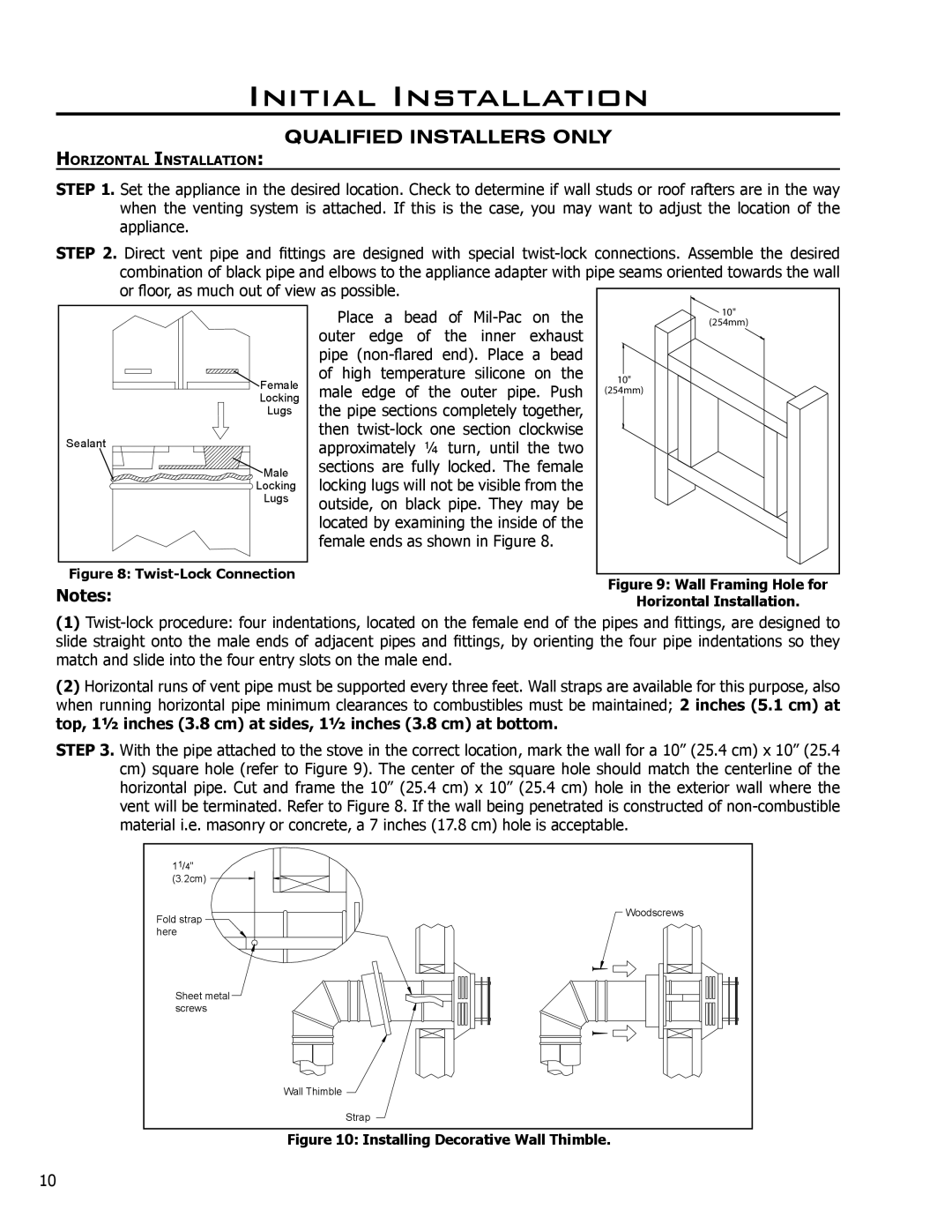
| female ends as shown in Figure 8. |
| ||||||
Figure 8: |
|
|
|
|
|
| Figure 9: Wall Framing Hole for | |
Notes: |
|
|
|
|
|
| ||
|
|
|
|
|
| Horizontal Installation. | ||
(1)
(2)Horizontal runs of vent pipe must be supported every three feet. Wall straps are available for this purpose, also when running horizontal pipe minimum clearances to combustibles must be maintained; 2 inches (5.1 cm) at top, 11⁄2 inches (3.8 cm) at sides, 11⁄2 inches (3.8 cm) at bottom.
STEP 3. With the pipe attached to the stove in the correct location, mark the wall for a 10” (25.4 cm) x 10” (25.4 cm) square hole (refer to Figure 9). The center of the square hole should match the centerline of the horizontal pipe. Cut and frame the 10” (25.4 cm) x 10” (25.4 cm) hole in the exterior wall where the vent will be terminated. Refer to Figure 8. If the wall being penetrated is constructed of
11/4" |
|
(3.2cm) |
|
Fold strap | Woodscrews |
| |
here |
|
Sheet metal |
|
screws |
|
| Wall Thimble |
| Strap |
Figure 10: Installing Decorative Wall Thimble.
10