Guide Dutilisation Manual DE Instrucciones
Dewalt
General Safety Rules For All Tools
Electrical Safety
Work Area
Service
Additional Specific Safety Instructions for Grinders
Personal Safety
Tool USE and Care
Always Wear EYE Protection When Using this Tool
Causes and Operator Prevention of Kickback
Switch Protection
Features
Clutch D28140, D28144, D28144N
Clutch
POWER-OFF Overload Protection
Components Fig
Complete Electronic Control
Rotating the Gear Case
Assembly and Adjustments
2 and 5 Grinding Wheels
Attaching Side Handle
2 and 5 Cutting Wheels
Wire Wheels
Accessories
Sanding Discs
Mounting Guard
2 and 5 Sanding Flap Discs
Mounting and Removing Guard
Operation
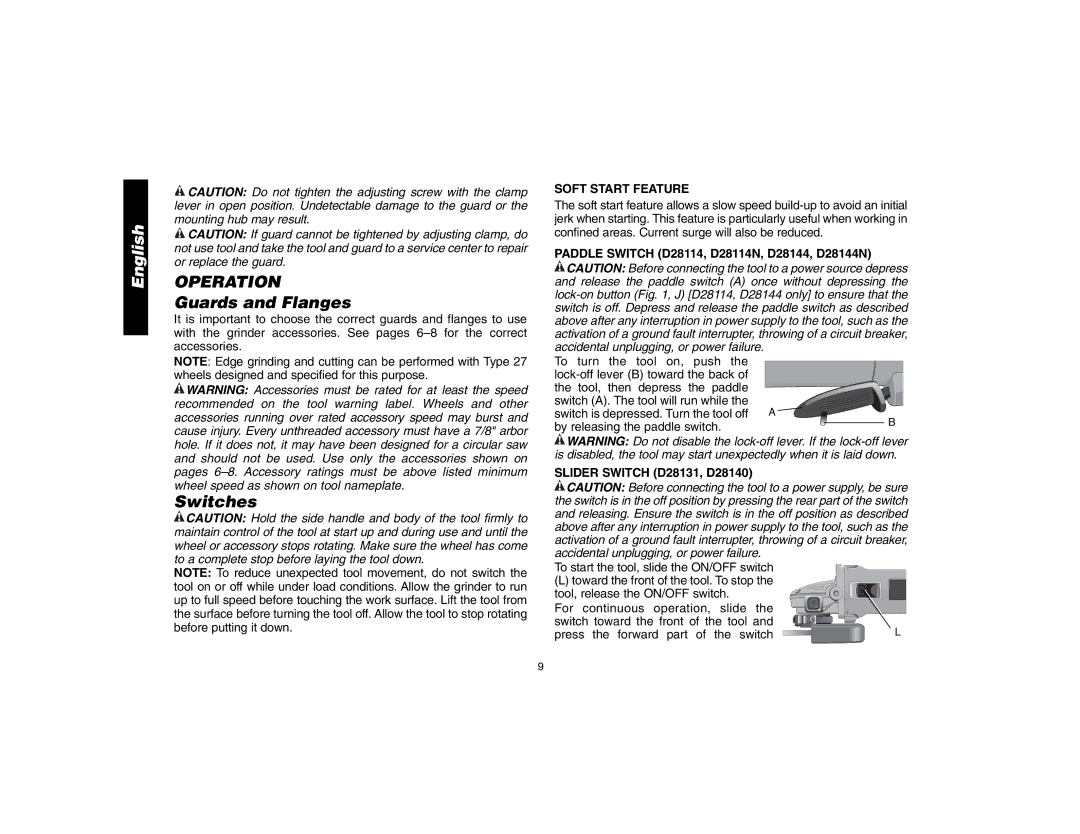
Switches
Soft Start Feature
Guards and Flanges
Mounting and Removing Hubbed Wheels
LOCK-ON Button D28114, D28144
Spindle Lock
Mounting NON-HUBBED Wheels
Sures caused by bending
Edge Grinding with Grinding Wheels
Surface Grinding with Grinding Wheels
Off. Allow the tool to stop rotating before laying it down
Creating gouges in the work surface
Using Sanding Backing Pads
Surface Finishing with Sanding Flap Discs
Mounting Sanding Backing Pads
Mounting Wire CUP Brushes and Wire Wheels
Mounting and Using Wire Brushes and Wire Wheels
Mounting and Using Cutting Type 1 Wheels
Using Wire CUP Brushes and Wire Wheels
On the gear case cover. You should be
Using Cutting Wheels
Mounting Cutting Wheels
Accessories Three Year Limited Warranty
Maintenance
Cleaning
Lubrication
English
Aire DE Travail
Règles de sécurité Généralités
Conserver CES Directives
Mesures DE Sécurité Électricité
Sécurité Personnelle
Calibre minimal des cordons de rallonge Tensi on
Utilisation ET Entretien DE L’OUTIL
Entretien
Causes de leffet de rebond et prévention par lopérateur
Embrayage Modèles D28140, D28144 ET D28144N
Composant E-SWITCH Protection Protection E-SWITCH
Caractéristiques
Dispositif E-CLUTCH
Composants fig
Fonction Complete Electronic Control
Capot protecteur pour
Disques de Ponçage
Capot protecteur pour Meule de type Bouton de
Meules de 114,3 mm et de 127 mm 4-1/2 et 5 po
Brosses métalliques à touret
Capot protecteur pour Meule de type
Accessoires
Assemblage ET Réglages
Assemblage DE LA Poignée Latérale
Capots protecteurs et brides
Assemblage du capot protecteur
Fonctionnement
Montage ET Démontage DU Capot Protecteur
Modèles D28114, D28114N, D28144 ET D28144N
Interrupteurs
Contacteur À Palette
Fonction DE Démarrage Souple
Dispositif DE Verrouillage DE LA Broche
Bouton DE Verrouillage
Modèles D28114 ET D28144
Broche lorsque loutil est éteint, débranché C
Meulage DE Surface Avec DES Meules Abrasives
Assemblage DE Meules Sans Moyeu
Mm 1/4 po dépaisseur, enfiler lécrou
Meulage DE Chant Avec DES Meules Abrasives
Finition DE Surface Avec DES Disques DE Ponçage À Lamelles
Assemblage DES Tampons Pour LE Ponçage
Utilisation DES Tampons Pour LE Ponçage
Assemblage et utilisation des brosses métalliques
Grains très fins pour la finition
Pour la retirer, inverser la procédure décrite ci-dessus
Assemblage et utilisation de disques de Type 1 coupe
Assemblage DE Brosses Coniques ET DE BROSSES-BOISSEAU
Utilisation DE Brosses Coniques ET DE BROSSES-BOISSEAU
Assemblage DE Disques DE Coupe
Utilisation DE Disques DE Coupe
Lubrification
Entretien
Nettoyage
Réparations
Contrat D’ENTRETIEN Gratuit D’UN AN
Garantie DE Remboursement DE 90 Jours
Área DE Trabajo
Instrucciones de seguridad generales
Conserve Estas Instrucciones
Seguridad Eléctrica
Amperaje
Calibre mínimo para cordones de extensión
Longitud total del cordón en metros
Seguridad Personal
Servicio
Causas del retroceso y su prevención por parte del operador
Características
Protección Contra Sobrecarga POWER-OFF
Embrague D28140, D28144, D28144N
Componentes Fig
Accesorios
Ensamblado Y Ajustes
Rotación de la caja de engranajes
Protector de montaje
Protector tipo Liberación del disco Quick-change
Tuerca de fijación Roscada Disco con cubo Tipo
Liberación del disco Quick-change
Discos de corte de 114,3 mm 2 y 127 mm
Discos de alambre
Con la palanca de la abrazadera en la posición de cerrada
Interruptores
Función DE Arranque Suave
Interruptor Deslizante D28131, D28140
Interruptor DE Paleta
D28114, D28114N, D28144, D28144N
Botón DE Bloqueo D28114, D28144
Montaje Y Extracción DE Discos CON Cubo
Montaje DE Discos SIN Cubo
Acabado DE Superficies CON Discos DE Lijar
Esmerilado DE Superficie CON Discos DE Esmerilar
Esmerilado DE Bordes CON Discos DE Esmerilar
Entre la herramienta y la superficie
Montaje DE LAS Almohadillas DE Respaldo Para Lijar
USO DE Almohadillas DE Respaldo Para Lijar
Para los cepillos de alambre con forma de copa
Montaje y uso de cepillos de alambre y discos de alambre
Montaje y uso de discos de corte Tipo
Superficie de trabajo
Montaje DEL Protector Cerrado Tipo
Montaje DE LOS Discos DE Corte
Lubricación
Mantenimiento
Limpieza
Reparaciones
AÑO DE Servicio Gratuito
Garantía limitada por tres años
Excepciones
Garantía DE Reembolso DE SU Dinero POR 90 Días
Especificaciones D28114, D28114N, D28131
D28140, D28144, D28144N