inward. To stop the tool while operating in continuous mode, press the rear part of the switch and release.
|
|
|
|
The |
|
|
|
comfort in extended use applications. |
|
|
|
To lock the tool on, push the |
|
|
|
lever (B) toward the back of the tool |
|
|
|
then depress the paddle switch (A). |
|
|
|
With the tool running, depress the lock- | A | B | J |
on button (J). The tool will continue to |
| ||
|
|
|
run after the paddle switch is released. To unlock the tool, depress and release the paddle switch. This will cause the tool to stop.
![]() CAUTION: Allow the tool to reach full speed before touching tool to the work surface. Lift the tool from the work surface before turn- ing the tool off.
CAUTION: Allow the tool to reach full speed before touching tool to the work surface. Lift the tool from the work surface before turn- ing the tool off.
SPINDLE LOCK
The spindle lock (C) is provided to prevent the spindle from rotat- ing when installing or removing wheels. Operate the spindle lock only when the tool is turned off, unplugged C ![]()
from the power supply, and has come to a complete stop. Do not engage the spindle lock while the tool is operating because
damage to the tool will result. To engage the lock, depress the spindle lock button and rotate the spindle until you are unable to rotate the spindle further.
Mounting and Using Depressed Center Grinding Wheels and Sanding Flap Discs
MOUNTING AND REMOVING HUBBED WHEELS
![]() CAUTION: Turn off and unplug the tool before making any adjustments or removing or installing attachments or acces- sories. Before reconnecting the tool, depress and release the paddle switch to ensure that the tool is off.
CAUTION: Turn off and unplug the tool before making any adjustments or removing or installing attachments or acces- sories. Before reconnecting the tool, depress and release the paddle switch to ensure that the tool is off.
Hubbed wheels install directly on the
1.Backing flange is retained to the grinder by an
2.Thread the wheel on the spindle by hand.
3.Depress the spindle lock button and use a wrench to tighten the hub of the wheel.
4.Reverse the above procedure to remove the wheel.
![]() CAUTION: Failure to properly seat the wheel before turning the tool on may result in damage to the tool or the wheel.
CAUTION: Failure to properly seat the wheel before turning the tool on may result in damage to the tool or the wheel.
MOUNTING NON-HUBBED WHEELS
![]() CAUTION: Turn off and unplug the tool before making any adjustments or removing or installing attachments or acces- sories. Before reconnecting the tool, turn the switch on and off as previously described to ensure that the tool is off.
CAUTION: Turn off and unplug the tool before making any adjustments or removing or installing attachments or acces- sories. Before reconnecting the tool, turn the switch on and off as previously described to ensure that the tool is off.
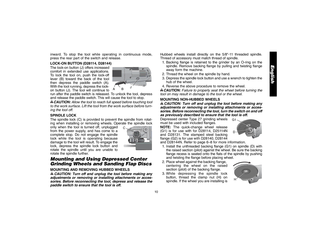
Depressed center Type 27 grinding wheels G1 | ||
must be used with included flanges. |
| |
NOTE: The |
| |
(G1) is for use with for D28114, D25114N | D | |
and D28131. The stamped steel backing | ||
| ||
flange (G2) is for use with D28140, D28144
and D28144N. Refer to page
1.Install the unthreaded backing flange (G1) on spindle (D) with the raised section (pilot) against the wheel. Be sure the backing flange recess is seated onto the flats of the spindle by pushing and twisting the flange before placing wheel.
2. Place wheel against the backing flange, centering the wheel on the raised section (pilot) of the backing flange.
3. While | depressing | the spindle lock |
| |
button, | thread the | clamp nut (H) on |
| |
H | ||||
spindle. If the wheel you are installing is | ||||
| ||||
English
10