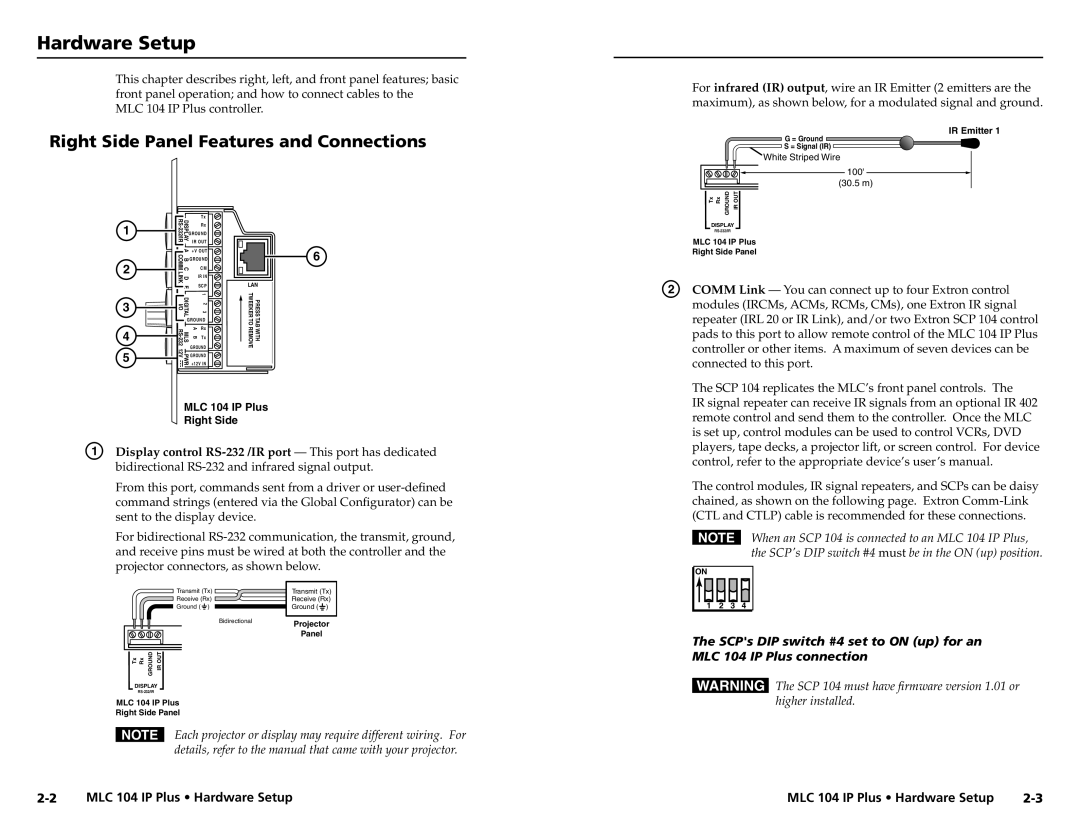
MLC 104 IP Plus specifications
The Epson MLC 104 IP Plus is a versatile and innovative printing solution designed to meet the needs of both businesses and individual users. This model stands out for its exceptional performance, reliability, and advanced features, making it an ideal choice for a variety of printing applications.One of the main features of the Epson MLC 104 IP Plus is its high-speed printing capability. With print speeds of up to 35 pages per minute, users can efficiently produce large volumes of documents without compromising quality. The printer utilizes PrecisionCore technology, which is Epson's proprietary printing technology that enhances speed and quality. This technology allows for precise ink placement, resulting in sharp text and vibrant images.
The Epson MLC 104 IP Plus also supports a variety of media types and sizes, including envelopes, labels, and various paper types, making it a flexible choice for different printing needs. It can handle paper sizes ranging from A6 to A4, allowing users to print everything from small labels to large reports.
Another key characteristic of this printer is its energy efficiency. The Epson MLC 104 IP Plus is designed to consume less power compared to traditional laser printers, making it an environmentally friendly option. Additionally, it features an automatic duplex printing function, which helps save paper and reduce waste.
Connectivity is another strong suit of the MLC 104 IP Plus. It offers multiple connectivity options, including USB, Ethernet, and wireless networking capabilities. This allows users to easily connect the printer to various devices, such as computers, smartphones, and tablets, streamlining the printing process. The included mobile printing solutions, such as Epson Email Print and the Epson iPrint app, make it even easier to print documents directly from mobile devices.
The Epson MLC 104 IP Plus is accompanied by a user-friendly interface, featuring a clear LCD screen that simplifies navigation through settings and options. This ease of use is complemented by low maintenance requirements, making it suitable for busy environments.
In summary, the Epson MLC 104 IP Plus combines high-speed printing, versatile media handling, energy efficiency, and robust connectivity options. With its PrecisionCore technology and user-friendly design, this printer is an excellent choice for those seeking a reliable and efficient printing solution. Whether for a home office or a larger business operation, the MLC 104 IP Plus delivers quality and performance that meets the demands of modern printing.

