Chapter 3
Communication Interfaces
Communication between a host and the printer can be performed in three communication interface: USB, Parallel or Serial
Communication cables are not supplied with the printer
Serial Interface
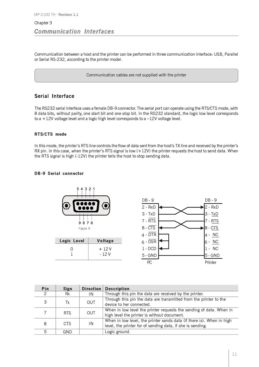
The RS232 serial interface uses a female
RTS/CTS mode
In this mode, the printer’s RTS line controls the flow of data sent from the host’s TX line and received by the printer’s RX pin. In this case, when the printer’s RTS signal is low (+12V) the printer requests the host to send data. When the RTS signal is high
Figura 9
Logic Level | Voltage |
0+ 12 V
1- 12 V
DB - 9 | DB - 9 | |||
2 | - RxD | 2 | - RxD | |
3 | - TxD | 3 | - TxD | |
7 | - RTS | 7 | - RTS | |
8 - CTS | 8 - CTS | |||
4 | - DTR | 4 - | NC | |
6 | - DSR | 6 - | NC | |
1 | - DCD | 1 | - | NC |
5 | - GND | 5 | - GND | |
| PC | Printer | ||
Pin | Sign | Direction | Description | |
2 | Rx | IN | Through this pin the data are received by the printer. | |
3 | Tx | OUT | Through this pin the data are transmitted from the printer to the | |
device to her connected. | ||||
|
|
| ||
7 | RTS | OUT | When in low level the printer requests the sending of data. When in | |
high level the printer is without document. | ||||
|
|
| ||
8 | CTS | IN | When in low level, the printer sends data (if there is). When in high | |
level, the printer for of sending data, if she is sending. | ||||
|
|
| ||
|
|
|
| |
5 | GND |
| Logic ground. |
11