H-100 specifications
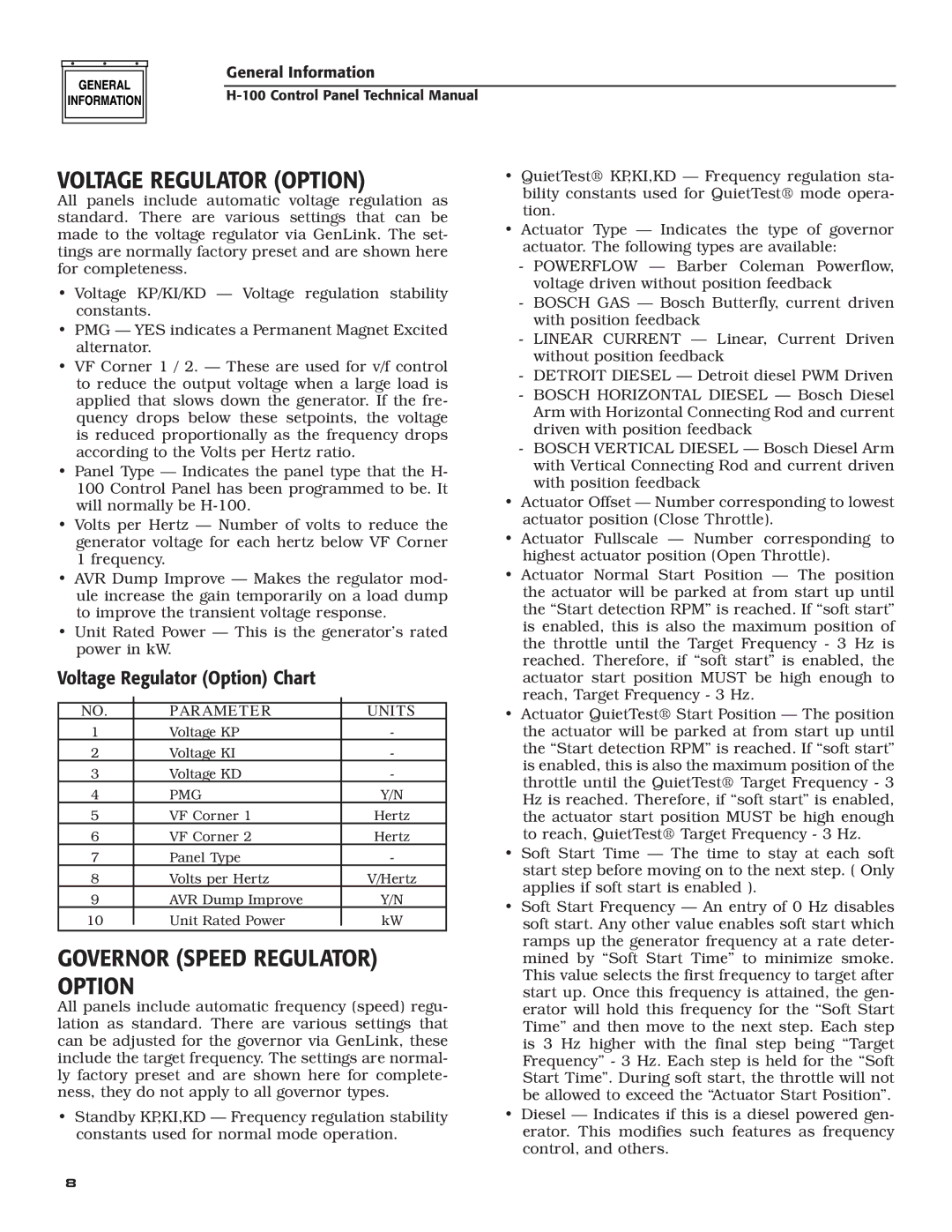
Generac Power Systems H-100 is an innovative and robust product that has garnered attention for its reliability and performance in power generation. This generator is primarily designed for both residential and commercial applications, providing a seamless backup power solution during outages.One of the standout features of the H-100 is its powerful engine. Equipped with a state-of-the-art gas engine, this generator can deliver up to 100 kW of power, ensuring that homes, businesses, and critical facilities remain operational even in the most challenging conditions. The engine is engineered for efficiency and longevity, reducing maintenance needs and minimizing fuel consumption.
Another significant aspect of the H-100 is its advanced Smart Management System. This technology ensures optimal power usage by intelligently distributing the electrical load among connected devices. By prioritizing essential circuits, the generator maximizes efficiency and prolongs operational time during power outages.
The H-100 also boasts a remarkable noise reduction feature. Its innovative design includes sound attenuation measures, allowing the generator to operate quietly, which is particularly beneficial in residential areas where noise pollution can be a concern. This focus on quieter operation enhances user comfort and complies with noise regulations.
Durability is a key characteristic of the Generac H-100. Constructed with high-quality materials, it is designed to withstand harsh weather conditions and heavy usage. This generator is built for longevity, providing users with reliable performance and peace of mind.
The H-100 is also equipped with a user-friendly control panel. This intuitive interface allows users to monitor the generator's performance, manage settings, and perform necessary maintenance checks easily. The integration of remote monitoring capabilities enables users to assess the generator's status from anywhere, adding an extra layer of convenience.
Lastly, Generac Power Systems offers comprehensive support and resources for H-100 users. Their commitment to customer service includes accessible informational materials, a reliable warranty program, and a national network of service professionals. This ensures that users receive the assistance they need to maintain their generators optimally.
In summary, the Generac Power Systems H-100 stands out as a reliable, efficient, and user-friendly power generation solution. With its robust engine, smart management system, noise reduction features, and durable construction, it is well-suited to meet the demands of both residential and commercial applications.

