AE/LZB 119 1902 R1A
TRANSMITTER
Transmit Frequency Generation
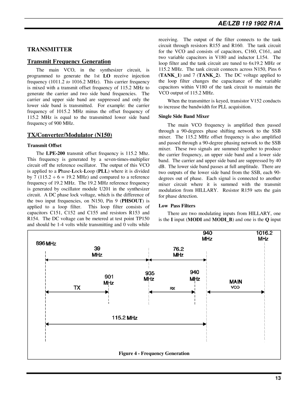
The main VCO, in the synthesizer circuit, is programmed to generate the 1st LO receive injection frequency (1011.2 to 1016.2 MHz). This carrier frequency is mixed with a transmit offset frequency of 115.2 MHz to generate the carrier and two side band frequencies. The carrier and upper side band are suppressed and only the lower side band is transmitted. For example: the carrier frequency of 1015.2 MHz minus the offset frequency of
115.2MHz is equal to the transmitted lower side band frequency of 900 MHz.
TX/Converter/Modulator (N150)
Transmit Offset
The
receiving. The output of the filter connects to the tank circuit through resistors R155 and R160. The tank circuit for the VCO and consists of capacitors, C160, C161, and two variable capacitors in V180 and inductor L154. The loop filter and the tank circuit are tuned to 6x19.2 MHz or
115.2MHz. The tank circuit connects across N150, Pins 6 (TANK_1) and 7 (TANK_2). The DC voltage applied to the loop filter changes the capacitance of the variable capacitors within V180 of the tank circuit to maintain the VCO output of 115.2 MHz.
When the transmitter is keyed, transistor V152 conducts to increase the bandwidth for PLL acquisition.
Single Side Band Mixer
The main VCO frequency is amplified then passed through a
Low Pass Filters
There are two modulating inputs from HILLARY, one is the I input (MODI and MODI_B) and one is the Q input
Figure 4 - Frequency Generation
13
