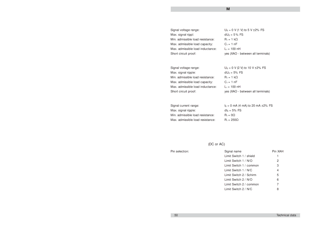
FC01-LQ specifications
ETA Systems FC01-LQ is a sophisticated compact computer designed for various applications in automation, data processing, and embedded systems. Its robust architecture and energy-efficient design make it suitable for both industrial and consumer uses. The FC01-LQ stands out in a crowded field of compact computing devices due to its unique features and advanced technologies.One of the most notable characteristics of the ETA Systems FC01-LQ is its low power consumption, which is crucial in applications where energy efficiency is paramount. This system leverages advanced power management technologies, allowing it to operate effectively while consuming minimal energy. This is particularly beneficial in environments where maintenance and energy costs are critical factors.
In terms of performance, the FC01-LQ is equipped with a powerful processor that ensures smooth operation and reliable performance across various tasks. It supports multiple processing cores, allowing for efficient multitasking capabilities. This makes it ideal for applications that require handling multiple data streams or executing several processes simultaneously.
Another key feature of the ETA Systems FC01-LQ is its extensive connectivity options. With multiple USB ports, Ethernet interfaces, and serial connection capabilities, this system can easily integrate into existing networks and work alongside other devices. This flexibility makes it an excellent choice for automation systems, IoT devices, and other networked applications.
The compact form factor of the FC01-LQ is another significant advantage. Its small size allows it to fit into tight spaces, making it perfect for embedded systems where real estate is limited. Despite its compact dimensions, it does not compromise on performance, delivering capabilities typically found in larger computer systems.
Built for durability and reliability, the FC01-LQ is designed to withstand harsh environmental conditions. It features a rugged casing that protects it from dust, moisture, and various temperature extremes. This durability ensures that it can operate effectively in industrial settings where equipment may be exposed to challenging conditions.
In summary, ETA Systems FC01-LQ is a powerful, energy-efficient, and compact computer solution that integrates advanced features and technologies. Its versatility makes it suitable for a wide range of applications, from industrial automation to consumer electronics. The combination of performance, adaptability, and durability positions the FC01-LQ as a go-to choice for those seeking a reliable embedded computing solution.
