Back Panel Connections
MONITOR
3
4
MAIN MONITOR : This connector is used for the Main monitor display, A number of different display modes may be selected for viewing.
CALL MONITOR : This connector is used for the Call(secondary) monitor. This monitor can only display full screen.
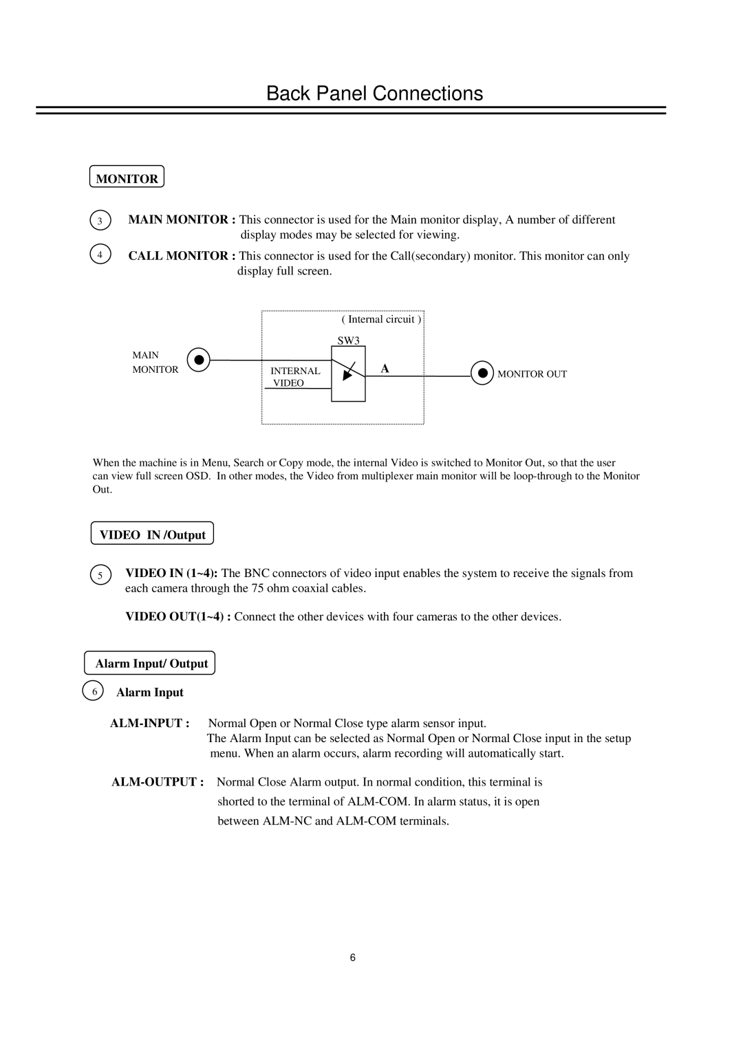
( Internal circuit )
SW3
MAIN |
| A |
|
MONITOR | INTERNAL | MONITOR OUT | |
| VIDEO |
|
|
When the machine is in Menu, Search or Copy mode, the internal Video is switched to Monitor Out, so that the user
can view full screen OSD. In other modes, the Video from multiplexer main monitor will be
VIDEO IN /Output
5VIDEO IN (1~4): The BNC connectors of video input enables the system to receive the signals from each camera through the 75 ohm coaxial cables.
VIDEO OUT(1~4) : Connect the other devices with four cameras to the other devices.
Alarm Input/ Output
6Alarm Input
The Alarm Input can be selected as Normal Open or Normal Close input in the setup menu. When an alarm occurs, alarm recording will automatically start.
6