Table 2. Front Panel Header Pins
| Pin | Signal |
|
|
|
HD_LED | 1 | HD_PWR |
|
|
|
| 3 | HDA# |
PWRLED | 2 | HDR_BLNK_GRN |
|
|
|
| 4 | HDR_BLNK_YEL |
RESET | 5 | GND |
|
|
|
| 7 | FP_RESET# |
PWRSW | 6 | SWITCH_ON# |
|
|
|
| 8 | GND |
No Connect | 9 | No Connect |
|
|
|
Empty | 10 | Empty |
|
|
|
In/Out |
| Description |
Out |
|
|
| Hard disk drive LED pulls up to +5V | |
Out |
|
|
| Hard disk drive active LED | |
Out |
| Front panel green light |
Out |
|
|
| Front panel yellow light | |
|
| Ground |
In |
|
|
| Reset switch | |
In |
| Power switch |
|
|
|
|
| Ground |
|
|
|
|
|
|
USB Headers
This motherboard contains six (6) USB 2.0 ports that are exposed on the rear panel of the chassis (Figure 2). The motherboard also contains one
1.Secure the bracket to either the front or rear panel of your chassis (not all chassis are equipped with the front panel option).
2.Connect the end of the cable to the USB 2.0 header on the motherboard.
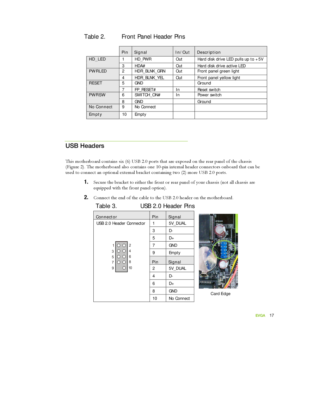
Table 3. USB 2.0 Header Pins
Connector | Pin | Signal |
USB 2.0 Header Connector | 1 | 5V_DUAL |
| 3 | D- |
| 5 | D+ |
| 7 | GND |
| 9 | Empty |
Pin |
| Signal |
2 |
| 5V_DUAL |
|
|
|
4 |
| D- |
|
| |
6 | D+ | |
|
| |
8 | GND | |
|
| |
10 | No Connect | |
Card Edge