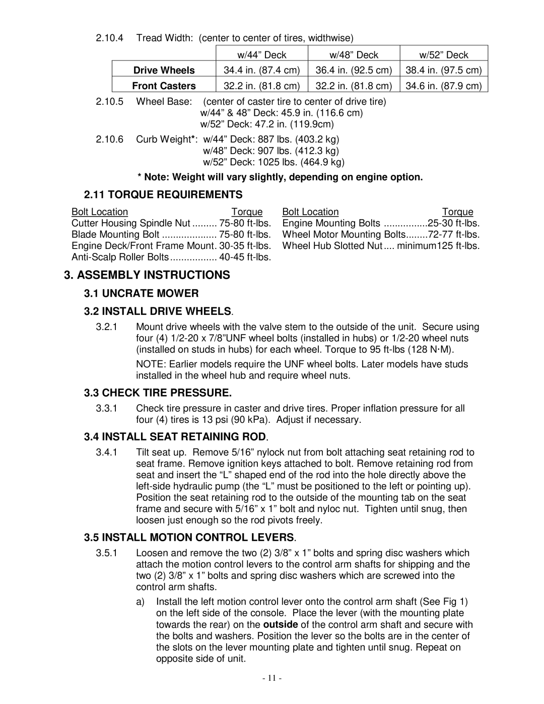
2.10.4Tread Width: (center to center of tires, widthwise)


w/44” Deck

w/48” Deck

w/52” Deck

Drive Wheels

34.4 in. (87.4 cm)

36.4 in. (92.5 cm)

38.4 in. (97.5 cm)

Front Casters

32.2 in. (81.8 cm)

32.2 in. (81.8 cm)

34.6 in. (87.9 cm)

2.10.5Wheel Base: (center of caster tire to center of drive tire) w/44” & 48” Deck: 45.9 in. (116.6 cm) w/52” Deck: 47.2 in. (119.9cm)

2.10.6Curb Weight*: w/44” Deck: 887 lbs. (403.2 kg)

w/48” Deck: 907 lbs. (412.3 kg)

w/52” Deck: 1025 lbs. (464.9 kg)

*Note: Weight will vary slightly, depending on engine option.

2.11TORQUE REQUIREMENTS

Bolt Location

Torque

Cutter Housing Spindle Nut

75-80 ft-lbs.

Blade Mounting Bolt

75-80 ft-lbs.

Engine Deck/Front Frame Mount. 30-35 ft-lbs.

Anti-Scalp Roller Bolts

40-45 ft-lbs.

Bolt Location

Torque

Engine Mounting Bolts

25-30 ft-lbs.

Wheel Motor Mounting Bolts

72-77 ft-lbs.

Wheel Hub Slotted Nut .... minimum125 ft-lbs.

3.ASSEMBLY INSTRUCTIONS

3.1UNCRATE MOWER

3.2INSTALL DRIVE WHEELS.

3.2.1Mount drive wheels with the valve stem to the outside of the unit. Secure using four (4) 1/2-20 x 7/8”UNF wheel bolts (installed in hubs) or 1/2-20 wheel nuts (installed on studs in hubs) for each wheel. Torque to 95 ft-lbs (128 N!M).

NOTE: Earlier models require the UNF wheel bolts. Later models have studs installed in the wheel hub and require wheel nuts.

3.3CHECK TIRE PRESSURE.

3.3.1Check tire pressure in caster and drive tires. Proper inflation pressure for all four (4) tires is 13 psi (90 kPa). Adjust if necessary.

3.4INSTALL SEAT RETAINING ROD.

3.4.1Tilt seat up. Remove 5/16” nylock nut from bolt attaching seat retaining rod to seat frame. Remove ignition keys attached to bolt. Remove retaining rod from seat and insert the “L” shaped end of the rod into the hole directly above the left-side hydraulic pump (the “L” must be positioned to the left or pointing up). Position the seat retaining rod to the outside of the mounting tab on the seat frame and secure with 5/16” x 1” bolt and nyloc nut. Tighten until snug, then loosen just enough so the rod pivots freely.

3.5INSTALL MOTION CONTROL LEVERS.

3.5.1Loosen and remove the two (2) 3/8” x 1” bolts and spring disc washers which attach the motion control levers to the control arm shafts for shipping and the two (2) 3/8” x 1” bolts and spring disc washers which are screwed into the control arm shafts.

a)Install the left motion control lever onto the control arm shaft (See Fig 1) on the left side of the console. Place the lever (with the mounting plate towards the rear) on the outside of the control arm shaft and secure with the bolts and washers. Position the lever so the bolts are in the center of the slots on the lever mounting plate and tighten until snug. Repeat on opposite side of unit.

- 11 -

Page 16
Image 16
Exmark LAZER ZTM manual Assembly Instructions

LAZER ZTM specifications

The Exmark Lazer ZTM represents a pinnacle of engineering excellence in the world of commercial zero-turn mowers. Renowned for its exceptional performance and durability, it is a favorite among landscaping professionals who require reliable equipment that can tackle the toughest mowing conditions.

At the heart of the Lazer ZTM is the powerful Kohler and Kawasaki engines that provide a range of horsepower options, ensuring that there is a configuration suitable for various mowing tasks. The efficiency of these engines is complemented by advanced cooling systems and heavy-duty air filtration, which helps to extend their life and optimize performance.

One of the standout features of the Lazer ZTM is its innovative UltraCut mowing deck. Available in various cutting widths, from 48 inches to 72 inches, the UltraCut deck is designed to deliver a premium cut quality across a range of grass types and conditions. Its unique design allows for superior airflow, resulting in better clipping dispersal and a clean cut. The adjustable cutting height provides operators with versatility, enabling them to tailor the height to specific requirements.

The Lazer ZTM is equipped with Exmark's innovative RED Technology, which stands for redesigned engine diagnostics. This smart technology allows operators to monitor the mower's performance in real time, providing crucial data on engine health, RPM, and fuel efficiency. This integration of technology enhances operational efficiency, limits downtime, and extends the lifespan of the mower.

Another hallmark of the Lazer ZTM is its robust construction. The frame is engineered from heavy-duty steel, ensuring longevity and resistance to wear and tear. Its commercial-grade components are designed to withstand the rigors of daily use, making it a reliable choice for professional landscapers.

Comfort and ergonomics also play a significant role in the Lazer ZTM’s design. The operator platform features a cushioned seat with adjustable armrests, providing comfort during extended mowing sessions. The control layout is intuitive, allowing for seamless operation and maneuverability in tight spaces.

Overall, the Exmark Lazer ZTM stands out for its combination of power, cutting efficiency, and operator comfort. Its commitment to innovation and quality makes it a leading choice for those looking to elevate their mowing experience. Whether for commercial landscaping or large property maintenance, the Lazer ZTM promises to deliver outstanding results.